 | –≠–ª–µ–∫—Ç—Ä–æ–Ω–Ω—ã–π –∫–æ–º–ø–æ–Ω–µ–Ω—Ç: MAX1758 | –°–∫–∞—á–∞—Ç—å:  PDF PDF  ZIP ZIP |

General Description
The MAX1758 is a switch-mode lithium-ion (Li+) battery
charger that charges one-to-four cells. It provides a reg-
ulated charging current accurate to ±10% and a regu-
lated voltage with only a ±0.8% total voltage error at the
battery terminals. The internal high-side switch delivers
a programmable current of up to 1.5A to charge the bat-
tery. The built-in safety timer automatically terminates
charging once the adjustable time limit has been
reached.
The MAX1758 regulates the voltage set point and
charging current using two loops that work together to
transition smoothly between voltage and current regula-
tion. An additional control loop monitors the total cur-
rent drawn from the input source (charging + system),
and automatically reduces battery-charging current,
preventing overload of the input supply and allowing
the use of a low-cost wall adapter.
The per-cell battery regulation voltage is set between
4.0V and 4.4V using standard 1% resistors. The num-
ber of cells is set from 1-to-4 by pin strapping. Battery
temperature is monitored by an external thermistor to
prevent charging outside the acceptable temperature
range.
The MAX1758 is available in a space-saving 28-pin
SSOP package. Use the MAX1758EVKIT to help reduce
design time. For a stand-alone charger with a 14V
switch, refer to the MAX1757 data sheet. For a charger
controller capable of up to 4A charging current, refer to
the MAX1737 data sheet.
________________________Applications
Features
o Stand-Alone Charger for Up to 4 Li+ Batteries
o ±0.8% Battery Regulation Voltage Accuracy
o Low-Dropout 98% Duty Cycle
o Safely Precharges Near-Dead Cells
o Continuous Voltage and Temperature Monitoring
o 0.1µA Shutdown Battery Current
o Input Voltage Up to 28V
o Up to 1.5A Programmable Charge Current
o Safety Timer Prevents Overcharging
o Input Current Limiting
o Space-Saving 28-Pin SSOP
o 300kHz PWM Oscillator Reduces Noise
MAX1758
Stand-Alone, Switch-Mode
Li+ Battery Charger with Internal 28V Switch
________________________________________________________________ Maxim Integrated Products
1
28
27
26
25
24
23
22
21
20
19
18
17
16
15
1
2
3
4
5
6
7
8
9
10
11
12
13
14
DCIN
CSSP
CSSN
CCV
CCI
CCS
FASTCHG
BST
CS
LX
LX
PGND
SHDN
FULLCHG
FAULT
TIMER2
TIMER1
CELL
HSD
HSD
BATT
VADJ
GND
REF
THM
ISETOUT
ISETIN
VL
SSOP
TOP VIEW
MAX1758
19-1752; Rev 1; 1/01
EVALUATION KIT
AVAILABLE
Ordering Information
28 SSOP
PIN-PACKAGE
TEMP. RANGE
-40∞C to +85∞C
MAX1758EAI
PART
Li+ Battery Packs
Notebook Computers
Hand-Held Instruments
Desktop Cradle Chargers
Pin Configuration
GND
DCIN
V
IN
6V TO 28V
CSSP
CSSN
LX
BST
VL
PGND
CS
BATT
THM
THERM
FASTCHG
FULLCHG
FAULT
HSD
SYSTEM
LOAD
Li+ BATTERY
1 TO 4 CELLS
MAX1758
ISETOUT
ISETIN
VADJ
CCS
CCI
CCV
REF
TIMER1
TIMER2
SHDN
ON
OFF
CELL
Typical Operating Circuit
For price, delivery, and to place orders, please contact Maxim Distribution at 1-888-629-4642,
or visit Maxim's website at www.maxim-ic.com.

MAX1758
Stand-Alone, Switch-Mode
Li+ Battery Charger with Internal 28V Switch
2
_______________________________________________________________________________________
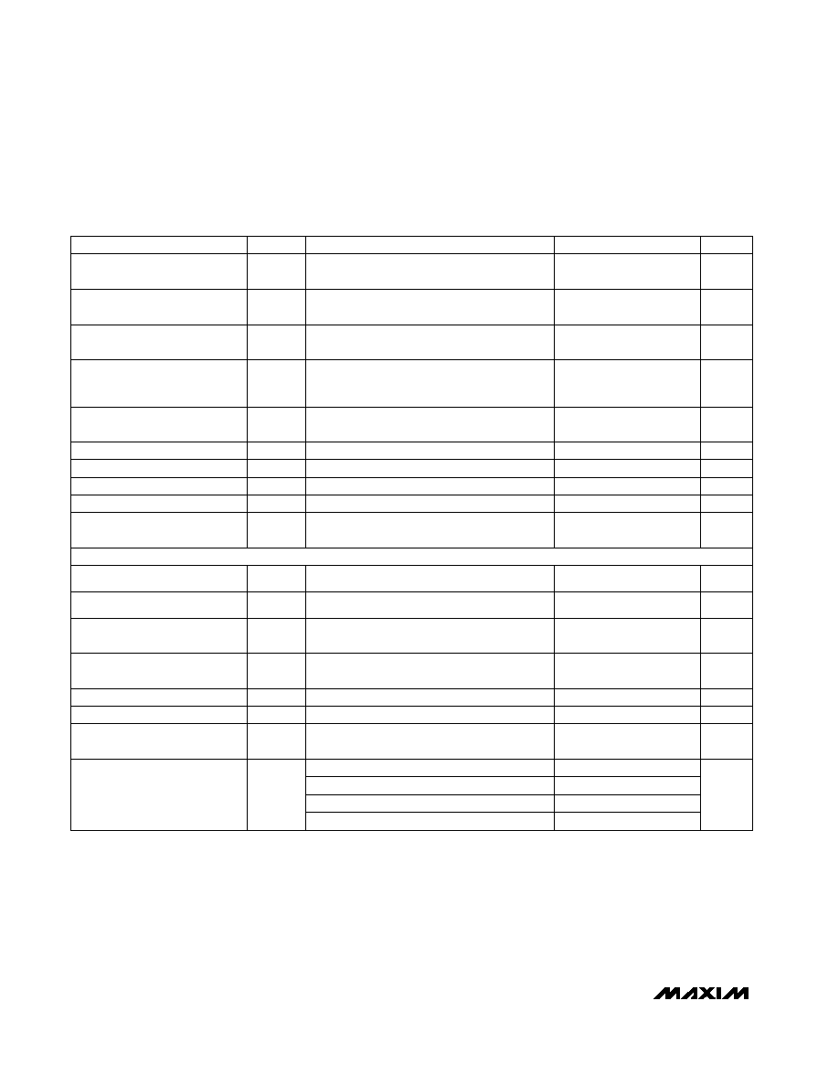
ABSOLUTE MAXIMUM RATINGS
ELECTRICAL CHARACTERISTICS
(Circuit of Figure 1, V
DCIN
= V
HSD
= V
CSSP
= V
CSSN
= 18V, V
SHDN
= V
VL
, V
CELL
= GND, V
BATT
= V
CS
= 4.2V, V
VADJ
= V
REF
/ 2,
V
ISETIN
= V
ISETOUT
= V
REF
, R
THM
= 10k
, T
A
= 0∞C to +85∞C, unless otherwise noted. Typical values are at T
A
= +25∞C.)
Stresses beyond those listed under "Absolute Maximum Ratings" may cause permanent damage to the device. These are stress ratings only, and functional
operation of the device at these or any other conditions beyond those indicated in the operational sections of the specifications is not implied. Exposure to
absolute maximum rating conditions for extended periods may affect device reliability.
DCIN, CSSP, CSSN, HSD to GND..........................-0.3V to +30V
CSSP to CSSN.......................................................-0.6V to +0.6V
BST to GND ............................................................-0.3V to +36V
BST to LX..................................................................-0.3V to +6V
LX to PGND ..............................................-0.6V to (V
HSD
+ 0.3V)
VL, SHDN, ISETIN, ISETOUT, REF, VADJ, CELL, TIMER1,
TIMER2, CCI, CCS, CCV, THM to GND ................-0.3V to +6V
FASTCHG, FULLCHG, FAULT to GND ..................-0.3V to +30V
BATT, CS to GND ...................................................-0.3V to +20V
CS to BATT Current ............................................................±3.5A
PGND to GND .......................................................-0.3V to +0.3V
VL Source Current...............................................................50mA
Continuous Power Dissipation (T
A
= +70∞C)
28-Pin SSOP (derate 9.5mW/∞C above +70∞C) ...........762mW
Operating Temperature Range ...........................-40∞C to +85∞C
Junction Temperature ......................................................+150∞C
Storage Temperature.........................................-65∞C to +150∞C
Lead Temperature (soldering, 10s) .................................+300∞C
V
BATT
= 18V, done state
Falling edge
CELL = REF, V
BATT
= 15V, any charging state
V
SHDN
= GND, V
BATT
= 19V
6V < V
DCIN
< 28V
Internal resistor between CS and BATT,
1.5A RMS operating
See PWM Controller section
V
BST
= V
LX
+ 4.5V
V
LX
= V
HSD
= V
DCIN
=28V, V
SHDN
= GND
I
REF
= 0 to 1mA
V
LX
= PGND, V
HSD
= V
DCIN
= 28V,
V
SHDN
= GND
V
CSSN
= V
CSSP
= V
DCIN
= 28V, V
SHDN
= GND
6V < V
DCIN
< 28V
Rising edge
6V < V
DCIN
< 28V
I
VL
= 0 to 15mA
In-dropout, f
OSC
/ 4
6V < V
DCIN
< 28V
Nondropout f
OSC
CONDITIONS
µA
150
270
BATT, CS Input Current
µA
280
540
µA
0.1
5
m
110
170
R
CS
CS to BATT Current-Sensing
Resistance
1
2
LX to PGND On-Resistance
m
260
450
HSD to LX On-Resistance
µA
0.1
10
LX Off-State Leakage
µA
0.1
10
HSD Off-State Leakage
µA
2
10
CSSN/CSSP Off-State Leakage
%
97
98
LX Maximum Duty Cycle
kHz
270
300
330
f
OSC
PWM Oscillator Frequency
V
0.075
0.125
0.175
DCIN to BATT Dropout
Threshold, DCIN Falling
mA
5
7
DCIN Quiescent Supply Current
mV
6
14
REF Load Regulation
mV
2
6
REF Line Regulation
V
4.179
4.20
4.221
V
0.20
0.30
0.40
DCIN to BATT Dropout
Threshold, DCIN Rising
V
5.10
5.40
5.70
VL Output Voltage
mV
44
65
V
REF
REF Output Voltage
UNITS
MIN
TYP
MAX
SYMBOL
PARAMETER
V
6
28
DCIN Input Voltage Range
SUPPLY AND REFERENCE
SWITCHING REGULATOR
VL Output Load Regulation

MAX1758
Stand-Alone, Switch-Mode
Li+ Battery Charger with Internal 28V Switch
_______________________________________________________________________________________
3
ELECTRICAL CHARACTERISTICS (continued)
(Circuit of Figure 1, V
DCIN
= V
HSD
= V
CSSP
= V
CSSN
= 18V, V
SHDN
= V
VL
, V
CELL
= GND, V
BATT
= V
CS
= 4.2V, V
VADJ
= V
REF
/ 2,
V
ISETIN
= V
ISETOUT
= V
REF
, R
THM
= 10k
, T
A
= 0∞C to +85∞C, unless otherwise noted. Typical values are at T
A
= +25∞C.)
V
ADJ
= GND
Instantaneous peak current limit
With 1% VADJ resistors
Not including VADJ resistor tolerances
CELL = float, GND, VL, or REF
CONDITIONS
3.948
3.979
4.010
BATT Regulation Voltage
Adjustment Range
-1
1
Absolute Voltage Accuracy
%
-0.8
0.8
V/cell
4.167
4.2
4.233
V
BATTR
Battery Regulation Voltage
V
0
19
BATT, CS Input Voltage Range
A
2.4
2.7
3.0
CS to BATT Hard Current Limit
UNITS
MIN
TYP
MAX
SYMBOL
PARAMETER
V
ADJ
= REF
V/cell
4.386
4.421
4.453
V
CCV
= 2V
mS
◊
cells
0.4
0.7
1.0
CCV Amplifier
Transconductance
V
CCV
= 2V
µA
±50
CCV Amplifier Maximum Output
Current
A
1.35
1.5
1.65
BATT Full-Scale Charge Current
V
ISETOUT
= V
REF
/ 10
mA
100
150
200
BATT 1/10-Scale Charge
Current (Note 1)
V
BATT
< 2.4V per cell
mA
100
150
200
BATT Charge Current in
Prequalification State
V
CCI
= 2V
µA/A
60
130
240
CCI Battery Current Sense Gain
V
CCI
= 2V
µA
±100
CCI Amplifier Maximum Output
Current
mV
90
100
115
CSSP to CSSN Full-Scale
Current-Sense Voltage
V
ISETIN
= V
REF
/ 10
mV
5
10
15
CSSP to CSSN 1/10-Scale
Current-Sense Voltage
V
CCS
= 2V
mS
1.0
2.0
3.0
CCS Amplifier Transconductance
mV
25
200
CCV Clamp Voltage with
Respect to CCI, CCS
THM low-temp or high-temp current
V
1.386
1.40
1.414
V
TRT
THM Trip Threshold Voltage
V
THM
= 1.4V
µA
46.2
49
51.5
I
TLTC
THM Low-Temp Current
V
THM
= 1.4V
µA
344
353
362
I
THTC
THM High-Temp Current
Combines THM low-temp current and THM
threshold, V
TRT
/ I
TLTC
k
26.92
28.70
30.59
THM COLD Threshold
Resistance (Note 2)
Combines THM high-temp current and THM
threshold, V
TRT
/ I
THTC
k
3.819
3.964
4.115
THM HOT Threshold Resistance
(Note 2)
VOLTAGE LIMIT ACCURACY
ERROR AMPLIFIERS
STATE MACHINE
V
CCS
= 2V
µA
±100
CCS Amplifier Maximum Output
Current
mV
25
200
CCI, CCS Clamp Voltage with
Respect to CCV
MAX1758
Stand-Alone, Switch-Mode
Li+ Battery Charger with Internal 28V Switch
4
_______________________________________________________________________________________
ELECTRICAL CHARACTERISTICS (continued)
(Circuit of Figure 1, V
DCIN
= V
HSD
= V
CSSP
= V
CSSN
= 18V, V
SHDN
= V
VL
, V
CELL
= GND, V
BATT
= V
CS
= 4.2V, V
VADJ
= V
REF
/ 2,
V
ISETIN
= V
ISETOUT
= V
REF
, R
THM
= 10k
, T
A
= 0∞C to +85∞C, unless otherwise noted. Typical values are at T
A
= +25∞C.)
CONDITIONS
% of
V
BATTR
x cell
94
95
96
BATT Recharge Voltage
Threshold (Note 6)
mA
250
330
400
FULLCHG BATT Current
Termination Threshold (Note 5)
V/cell
4.55
4.67
4.8
BATT Overvoltage Threshold
(Note 4)
V/cell
2.4
2.5
2.6
BATT Undervoltage Threshold
(Note 3)
UNITS
MIN
TYP
MAX
SYMBOL
PARAMETER
TIMER1 and TIMER2
Oscillation Frequency
2.1
2.33
2.6
kHz
Prequalification Timer
6.25
7.5
8.75
Fast-Charge Timer
81
90
100
Full-Charge Timer
81
90
100
Top-Off Timer
40.5
45
49.8
Temperature Measurement
Frequency
0.98
1.12
1.32
Hz
SHDN Input Voltage High
V
IH
1.4
V
SHDN Input Voltage Low
V
IL
0.6
V
VADJ, ISETIN, ISETOUT Input
Voltage Range
0
V
REF
V
V
VADJ
, V
ISETIN
, V
ISETOUT
= 0 or 4.2V
nA
SHDN Input Bias Current
V
SHDN
= 0 or V
VL
-1
1
µA
ISETOUT Shutdown Threshold
Voltage (Note 3)
150
220
300
mV
CELL Input Bias Current
V
CELL
= 0 or V
VL
-5
5
µA
VADJ, ISETIN, ISETOUT Input
Bias Current
CELL Input Voltage
For 1 cell
0
0.5
For 3 cells
V
REF
- 0.3
V
REF
+ 0.3
For 2 cells (floating)
1.5
2.5
-50
50
CONTROL INPUTS/OUTPUTS
min
min
min
min
V
V
VL
- 0.4
V
VL
For 4 cells
MAX1758
Stand-Alone, Switch-Mode
Li+ Battery Charger with Internal 28V Switch
_______________________________________________________________________________________
5
ELECTRICAL CHARACTERISTICS (continued)
(Circuit of Figure 1, V
DCIN
= V
HSD
= V
CSSP
= V
CSSN
= 18V, V
SHDN
= V
VL
, V
CELL
= GND, V
BATT
= V
CS
= 4.2V, V
VADJ
= V
REF
/ 2,
V
ISETIN
= V
ISETOUT
= V
REF
, R
THM
= 10k
, T
A
= 0∞C to +85∞C, unless otherwise noted. Typical values are at T
A
= +25∞C.)
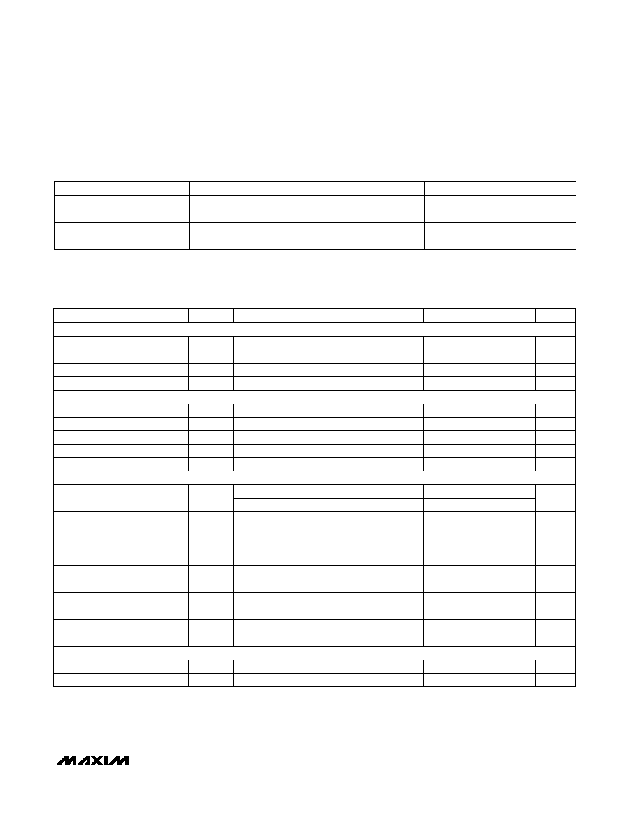
ELECTRICAL CHARACTERISTICS
(Circuit of Figure 1, V
DCIN
= V
HSD
= V
CSSP
= V
CSSN
= 18V, V
SHDN
= V
VL
, V
CELL
= GND, V
BATT
= V
CS
= 4.2V, V
VADJ
= V
REF
/ 2,
V
ISETIN
= V
ISETOUT
= V
REF
, R
THM
= 10k
, T
A
= -40∞C to +85∞C, unless otherwise noted.) (Note 7)
CONDITIONS
DCIN Input Voltage Range
6
28
V
UNITS
MIN
TYP
MAX
SYMBOL
PARAMETER
VL Output Voltage
5.1
5.7
V
REF Output Voltage
6V < V
DCIN
< 28V
4.166
4.242
V
REF Line Regulation
6V < V
DCIN
< 28V
6
mV
PWM Oscillator Frequency
f
OSC
Nondropout f
OSC
260
340
kHz
HSD to LX On-Resistance
V
BST
= V
LX
+ 4.5V
450
m
LX to PGND On-Resistance
2
CS to BATT Hard Current Limit
Instantaneous peak current limit
2.2
3.2
A
BATT, CS Input Voltage Range
0
19
V
Absolute Voltage Accuracy
Not including VADJ resistor tolerances
-0.8
0.8
%
With 1% VADJ resistors
-1
1
CSSP to CSSN 1/10-Scale
Current-Sense Voltage
V
SETIN
= V
REF
/ 10
5
15
mV
THM Trip Threshold Voltage
V
TRT
THM low - temp or high-temp current
1.386
1.414
V
THM Low-Temp Current
I
TLTC
V
THM
= 1.4V
46.2
51.5
µA
V
FASTCHG
, V
FULLCHG
, V
FAULT
= 28V,
V
SHDN
= GND
I
SINK
= 5mA
CONDITIONS
µA
1
FASTCHG, FULLCHG, FAULT
Output High Leakage
V
0.5
V
OL
FASTCHG, FULLCHG, FAULT
Output Low Voltage
UNITS
MIN
TYP
MAX
SYMBOL
PARAMETER
SUPPLY AND REFERENCE
SWITCHING REGULATOR
ACCURACY AND ERROR AMPLIFIERS
STATE MACHINE
BATT Regulation Voltage
CELL = float, GND, VL, or REF
4.158
4.242
V/cell
BATT Full-Scale Charge Current
1.3
1.7
A
BATT 1/10-Scale Charge
Current (Note 1)
V
SETOUT
= V
REF
/ 10
100
200
mA
BATT Charge Current in
Prequalification State
V
BATT
< 2.4V per cell
100
200
mA
CSSP to CSSN Full-Scale
Current-Sense Voltage
85
115
mV