
General Description
The MAX2472/MAX2473 evaluation kits (EV kits) simpli-
fy evaluation of the MAX2472/MAX2473 VCO buffers.
They enable performance testing and require no addi-
tional support circuitry. All inputs and outputs use SMA
connectors to facilitate connection of RF test equip-
ment.
The MAX2472 EV kit is assembled with the MAX2472
and provides a high-impedance input and a pair of
open-collector outputs. The EV kit includes a matching
network tuned for 900MHz. The MAX2473 EV kit is
assembled with the MAX2473 and provides a high-
impedance input, a single open-collector output, and a
bias control input for setting the output power. Output
matches for 600MHz, 1900MHz, or 2400MHz are
achieved by replacing the matching components with
values provided in the MAX2472/MAX2473 data sheet.
Features
o
Easy Evaluation of MAX2472/MAX2473
o
+2.7V to +5.5V Single-Supply Operation
o
Variable Bias Control (MAX2473)
o
Single (MAX2473) or Dual (MAX2472) Open-
Collector Outputs
o
All Critical Peripheral Components Included
Evaluate: MAX2472/MAX2473
MAX2472/MAX2473 Evaluation Kits
________________________________________________________________
Maxim Integrated Products
1
19-1466; Rev 0; 6/99
MAX2472
Component List
MAX2473
Component List
PART
MAX2472
EVKIT
MAX2473
EVKIT -40∞C to +85∞C
-40∞C to +85∞C
TEMP. RANGE
IC
PACKAGE
SOT23-6
SOT23-6
For free samples & the latest literature: http://www.maxim-ic.com, or phone 1-800-998-8800.
For small orders, phone 1-800-835-8769.
Ordering Information
SMA connectors (PC edge-mount)
EF Johnson 142-0701-801
3
IN, OUT1,
OUT2
Test points
2
VCC, GND
Not installed
0
JU1
0
resistors (0603)
2
R6, R7
Not installed
0
R1≠R5
12nH 5% inductor (0603)
Coilcraft 0603HS-12NTJBC
1
Z1
DESIGNATION
12nH 5% inductor (0603)
Coilcraft 0603HS-12NTJBC
1
L1
1µF 5% ceramic capacitor (0805)
1
C10
100pF 5% ceramic capacitors (0603)
Murata GRM39COG101J50V
4
C3, C6, C7, C8
0.01µF 5% ceramic capacitors (0603)
Murata GRM39X7R103J50V
3
C2, C5, C9
1pF ±0.1pF ceramic capacitors
(0603) Murata GRM39COG1R0B50V
2
C1, C4
DESCRIPTION
QTY
SOT
TOP MARK
AAAZ
AABA
MAX2472EUT
(6-pin SOT23, top mark AAAZ)
1
U1
MAX2472/MAX2473 PC board
1
None
MAX2473EUT
(6-pin SOT23, top mark AABA)
1
U1
MAX2472/MAX2473 PC board
1
None
SMA connectors (PC edge-mount)
EF Johnson 142-0701-801
2
IN, OUT1
Test points
2
VCC, GND
15k
5% resistor (0603)
1
R3
11k
5% resistor (0603)
1
R2
0
resistors (0603)
2
R1, R6
0
resistor (0603)
1
Z1
DESIGNATION
12nH 5% inductor (0603)
Coilcraft 0603HS-12NTJBC
1
L1
Not installed
0
C4, C5, C6
100pF 5% ceramic capacitors (0603)
Murata GRM39COG101J50V
3
C3, C7, C8
0.01µF 5% ceramic capacitors (0603)
Murata GRM39X7R103J50V
2
C2, C9
1pF ±0.1pF ceramic capacitor (0603)
Murata GRM39COG1R0B50V
1
C1
DESCRIPTION
QTY
1µF 5% ceramic capacitor (0805)
1
C10
6-pin header
1
JU1
23k
5% resistor (0603)
1
R4
Not installed
0
R5, R7
Shunt (JU1)
1
None
Evaluate: MAX2472/MAX2473
MAX2472/MAX2473 Evaluation Kits
2
_______________________________________________________________________________________
_________________________Quick Start
The MAX2472/MAX2473 EV kits are fully assembled
and factory tested. Follow the instructions in the
Connections and Setup section for proper device eval-
uation.
Test Equipment Required
This section lists the test equipment recommended to
verify operation of the MAX2472/MAX2473. It is intend-
ed as a guide only, and some substitutions are possi-
ble.
∑
DC power supply capable of supplying a minimum
of 10mA at +2.7V to +5.5V
∑
RF spectrum analyzer capable of making measure-
ments over the bandwidth of the MAX2472/MAX2473
as well as a few harmonics (if desired), such as the
6GHz HP8561E
∑
RF signal generator capable of delivering 0dBm out-
put power from 500MHz to 2500MHz, such as the
HP8648C signal generator
∑
50
SMA termination
∑
Two 50
SMA cables
Connections and Setup
1) Verify the DC power supply is set to no more than
+5.5V and is off before connecting the supply to the
EV kit. A good starting voltage is +3.0V. Connect the
power supply between V
CC
and GND, then turn on
the power supply.
2) Set the output power of the signal generator to
-20dBm at 900MHz. Disable the generator's output,
then connect the output of the signal generator to
the IN SMA connector of the MAX2472/MAX2473 EV
kit board. For the MAX2472, terminate OUT2 with a
50
termination. For the MAX2473, set the center
jumper at JU1 to set R
BIAS
= 15k
.
3) Connect OUT1 to the spectrum analyzer's RF input.
Analysis
1) Adjust the frequency span, center frequency, and
amplitude of the spectrum analyzer to observe the
signal peak at 900MHz; the output signal power
should read approximately -9dBm. The first harmon-
ic (1800MHz) will be approximately -35dBm
(-25dBc).
_______________Detailed Description
This section describes the circuitry surrounding the IC
in the MAX2472/MAX2473 EV kits. For more detailed
information covering device operation, please consult
the MAX2472/MAX2473 data sheet.
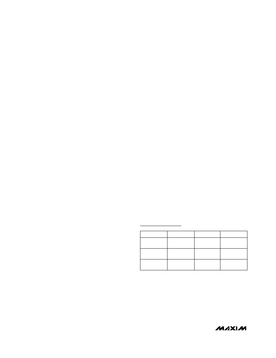
Figure 1 shows the schematic for the MAX2472/
MAX2473 EV kits. Input capacitors C7 and C8 are
100pF DC-blocking capacitors; this value contributes
minimal reactance to the signal paths, down to
500MHz. Capacitors C9 and C10 form the V
CC
decou-
pling network. Note the location of each component; a
relatively large 1µF tantalum capacitor, C10, is located
near the V
CC
connector. Placed near the device, a sub-
stantially smaller 0.01µF decoupling capacitor, C9,
reduces any high-frequency interference. The EV kits
include pad R5 to facilitate simple termination of the
input.
Both the MAX2472 and MAX2473 EV kits feature a bias
and tuning network at OUT1. Capacitors C2 and C3
form an output bias supply decoupling network.
Inductor L1 acts as an RF choke while providing DC
bias and, in conjunction with C1, forms a narrowband
matching network. The EV kits are output matched for
900MHz operation. The MAX2472 has an identical bias-
supply decoupling network and matching network for
OUT2. For the MAX2473, OUT2's matching network is
replaced with a set of jumpers to allow the selection of
a bias resistor for the BIAS pin. Set the appropriate
jumper at JU1 to select between 11k
, 15k
, or 23k
(R2, R3, and R4, respectively).
Component Suppliers
SUPPLIER
PHONE
FAX
Coilcraft
800-322-2645 847-639-1469
E.F. Johnson
402-474-4800 402-474-4858
Murata
770-436-1300 770-436-3030
URL
http://www.
coilcraft.com
http://www.ef
johnson.com
http://www.
murata.com
Evaluate: MAX2472/MAX2473
MAX2472/MAX2473 Evaluation Kits
_______________________________________________________________________________________
3
MAX2472
MAX2473
V
CC
V
CC
C9
0.01
µ
F
6
5
4
1
2
3
C8
100pF
R5
OPEN
C7
100pF
C10
1
µ
F
VCC
GND
SMA
IN
SMA
OUT1
SMA
OUT2
OUT1
L1
12nH
C3
100pF
C2
0.01
µ
F
VCC
R6
0
GND
GND
IN
U1
OUT2
Z1
C5
C4
1pF
C1
1pF
R1
R4
R3
R2
JU1
1
3
5
2
4
6
C6
*REFER TO APPROPRIATE COMPONENT LIST
FOR COMPONENT VALUES.
R7
*
*
*
*
*
*
*
*
Figure 1. MAX2472/MAX2473 EV Kit Schematic
1.0"
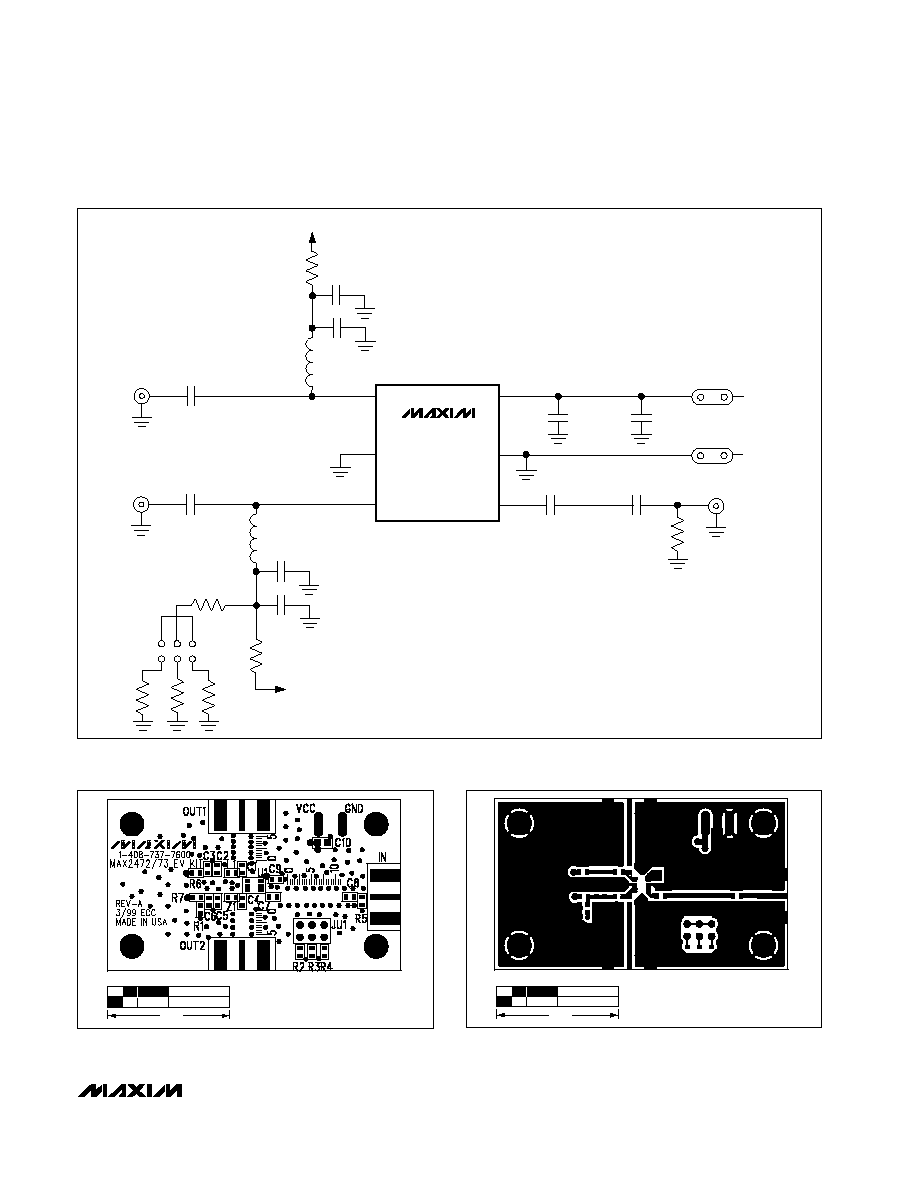
Figure 2. MAX2472/MAX2473 EV Kit Component Placement
Guide--Top Silkscreen
1.0"
Figure 3. MAX2472/MAX2473 EV Kit PC Board Layout--
Component Side

Evaluate: MAX2472/MAX2473
MAX2472/MAX2473 Evaluation Kits
Maxim cannot assume responsibility for use of any circuitry other than circuitry entirely embodied in a Maxim product. No circuit patent licenses are
implied. Maxim reserves the right to change the circuitry and specifications without notice at any time.
4
_____________________Maxim Integrated Products, 120 San Gabriel Drive, Sunnyvale, CA 94086 408-737-7600
© 1999 Maxim Integrated Products
Printed USA
is a registered trademark of Maxim Integrated Products.
Figure 4. MAX2472/MAX2473 EV Kit PC Board Layout--Main
Ground Plane
Figure 5. MAX2472/MAX2473 EV Kit PC Board Layout--V
CC
Plane
Figure 6. MAX2472/MAX2473 EV Kit PC Board Layout--Solder
Side
1.0"
1.0"
1.0"