
General Description
The MAX2644 evaluation kit (EV kit) simplifies the evalu-
ation of the MAX2644 low-noise amplifier (LNA). The kit
enables testing of the device's performance and
requires no additional support circuitry. The signal input
and output use SMA connectors to facilitate easy con-
nection of RF test equipment.
The MAX2644 EV kit is fully assembled with the
MAX2644 and incorporates matching components opti-
mized for a 2450MHz RF frequency operation.
Features
o Easy Evaluation of MAX2644
o +2.7V to +5.5V Single-Supply Operation
o Matched to 50 at 2450MHz
o Fully Assembled and Tested
Evaluates: MAX2644
MAX2644 Evaluation Kit
________________________________________________________________ Maxim Integrated Products
1
19-1786; Rev 0; 3/01
Ordering Information
For pricing, delivery, and ordering information, please contact Maxim/Dallas Direct! at
1-888-629-4642, or visit Maxim's website at www.maxim-ic.com.
PART
TEMP RANGE
IC-PACKAGE
MAX2644EVKIT
-40
∞C to +85∞C
8 SC70-6
Quick Start
The MAX2644 EV kit is fully assembled and factory test-
ed. Follow the instructions in the Connections and
Setup section for proper device evaluation.
Test Equipment Required
∑
One RF signal generator capable of delivering
10dBm of output power and a frequency range
covering the MAX2644 (2400MHz to 2500MHz, for
example)
∑
An RF spectrum analyzer that covers the operating
frequency range (HP8561E, for example)
∑
DC power supply capable of supplying +2.7V to
+5.5V and 20mA of current
∑
Two 50
coaxial cables with SMA connectors
∑
(Optional) An ammeter to measure supply current
∑
(Optional) A noise figure meter
∑
(Optional) Network analyzer to measure gain and
return loss
Connections and Setup
Checking Power Gain
1) Connect a DC supply (preset to +3.0V) to the VCC
and GND terminals (through an ammeter, if desired)
on the EV kit.
2) Set the RF generator for a 2450MHz output frequen-
cy at a -30dBm power level. Disable RF generates
DESIGNATION
QTY
DESCRIPTION
C1, C2
2
33pF
±5%, 50V ceramic
capacitors (0402)
Murata GRM36C0G330J050AD
or
Taiyo Yuden UMK105CH330JW
C3
1
2.2pF ±0.1pF, 50V ceramic
capacitor (0402)
Murata GRM36C0G2R2B050AD
or
Taiyo Yuden UMK105CH2R2CW
L1
1
3.3nH
±0.3nH inductor (0402)
Murata LQG10A3N3S00 or
Coilcraft 0402CS-3N3XKBG
R1
1
1.2k
±5% resistor (0402)
RFIN, RFOUT
2
SMA connectors
(PC edge-mount)
EFJohnson 142-0701-801 or
Digi-Key J502-ND
VCC, GND
2
Test points, Mouser 151-203
U1
1
MAX2644EXT (6-pin SC70)
None
1
MAX2644EVKIT PC board
None
1
MAX2644 EV kit data sheet
None
1
MAX2644 data sheet
SUPPLIER
PHONE
FAX
WEBSITE
Coilcraft
847-639-6400
847-639-1469
www.coilcraft.com
Kamaya
219-489-1533
219-489-2261
www.kamaya.com
Murata Electronics
800-831-9172
814-238-0490
www.murata.com
Taiyo Yuden
800-348-2496
408-434-0375
www.t-yuden.com
Component Suppliers
Component List

output. Connect the RF generator output to the RFIN
SMA connector with a coaxial cable.
3) Connect the coaxial cable from the RFOUT SMA
connector to the spectrum analyzer.
4) Turn on the DC supply. The supply current should
read approximately 10mA (if using an ammeter).
5) Activate the RF generator's output. A signal on the
spectrum analyzer's display should indicate a typi-
cal gain of +17dB after accounting for cable and
board losses. Typical board loss is 0.6dB from input
to output port.
6) (Optional) Another method for determining gain is
using a network analyzer. This has the advantage of
displaying gain versus a swept frequency band, in
addition to displaying input and output return loss.
Refer to the network analyzer manufacturer's user
manual for setup details.
Checking Noise Figure
Noise figure measurements on low-noise devices such
as the MAX2644 are extremely sensitive to board and
lab setup losses and parasitics. There are many tech-
niques and precautions for measuring a low noise fig-
ure. Detailed explanation of these items would exceed
the scope of this document. Take into account PC-
board and external-components loss when performing
noise-figure measurements. The typical input losses on
this EV kit are 0.3dB. For more information on how to
perform this level of noise-figure measurement, refer to
the noise-figure meter operating manual as well as the
Agilent Technologies (formerly Hewlett Packard) appli-
cation note #57-2, "Noise Figure Measurement
Accuracy."
Layout Considerations
A good PC board layout is an essential part of an RF
circuit design. The EV kit PC board can serve as a
guide for laying out a board using the MAX2644.
Generally, the V
CC
node on the PC board should have
a decoupling capacitor located close to the device,
and additional capacitors may be needed for long V
CC
lines. This minimizes supply coupling. Proper ground-
ing of the GND pins is essential. Connect the GND pins
to the ground plane either directly or through vias or
both.
Evaluates: MAX2644
MAX2644 Evaluation Kit
2
_______________________________________________________________________________________
U1
MAX2644
SMA
RFIN
SMA
RFOUT
C1
33pF
L1
3.3nH
3
2
1
R1
1.2k
6
5
4
V
CC
GND
C3
2.2pF
C2
33pF
VCC
GND
RFIN
GND
RFOUT
BIAS
Length = 400mils
Figure 1. MAX2644 EV Kit Schematic
MAX2644 Evaluation Kit
Evaluates: MAX2644
Maxim cannot assume responsibility for use of any circuitry other than circuitry entirely embodied in a Maxim product. No circuit patent licenses are
implied. Maxim reserves the right to change the circuitry and specifications without notice at any time.
Maxim Integrated Products, 120 San Gabriel Drive, Sunnyvale, CA 94086 408-737-7600 ____________________
3
© 2001 Maxim Integrated Products
Printed USA
is a registered trademark of Maxim Integrated Products.
MAX2644 Evaluation Kit
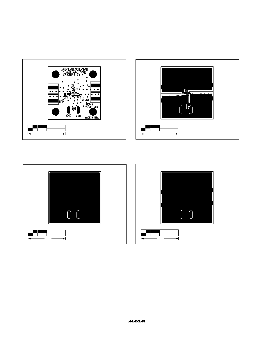
Figure 2. MAX2644 EV Kit Component Placement Guide--
Component Side
Figure 3. MAX2644 EV Kit PC Board Layout--Component Side
1.0"
1.0"
Figure 4. MAX2644 EV Kit PC Board Layout--Solder Side
1.0"
Figure 5. MAX2644 EV Kit PC Board Layout--Ground Plane
Layers 2 and 3
1.0"