MAX2820EV
General Description
The MAX2820/MAX2821 evaluation kits (EV kits) simplify
testing of the MAX2820/MAX2821. The EV kits provide
50
SMA connectors for all RF and baseband inputs and
outputs. Differential-to-single-ended and single-ended-to-
differential line drivers are provided to convert the differ-
ential I/Q baseband inputs and outputs to single ended.
The EV kits simplify evaluation of the MAX2820/
MAX2821s' receive and transmit performance in 802.11b
applications operating in the 2.4GHz to 2.5GHz ISM band.
Features
On-Board Line Drivers and Voltage Reference
50 SMA Connectors on All RF and Baseband
Ports
PC Control Software Available at
www.maxim-ic.com
SPITM/QSPITM/MICROWIRETM Compatible
Evaluate: MAX2820/MAX2821
MAX2820/MAX2821 Evaluation Kits
________________________________________________________________ Maxim Integrated Products
1
19-2581; Rev 0; 9/02
Component List
For pricing, delivery, and ordering information, please contact Maxim/Dallas Direct! at
1-888-629-4642, or visit Maxim's website at www.maxim-ic.com.
Ordering Information
SPI and QSPI are trademarks of Motorola, Inc.
MICROWIRE is a trademark of National Semiconductor Corp.
PART
TEMP RANGE
IC PACKAGE
MAX2820EVKIT
-40
�C to +85�C
48 QFN
MAX2821EVKIT
-40
�C to +85�C
48 QFN
DESIGNATION
QTY
DESCRIPTION
C1, C3, C7,
C10�C16,
C20�C23, C25,
C26, C28, C29,
C33, C34, C35,
C40, C50, C51
24
0.01�F
�10% ceramic capacitors
(0402)
Murata GRP155R71C103K
C2, C4, C5,
C6, C8, C9,
C17, C18, C19,
C27, C36�C39,
C41�C45
19
0.1�F
�10% capacitors (0402)
Murata GRP155R61A104K
C24, C46, C47,
C48
4
10�F
�10%, 16V tantalum capacitors,
C case
AVX TAJC106K016
C30
1
82pF
�5% capacitor (0402)
Murata GRP1555C1H820J
C31
1
100pF
�5% capacitor (0402)
Murata GRP1555C1H101J
C32
1
2000pF
�10% capacitor (0402)
Murata GRP155R71H202K
C49
1
20pF
�5% capacitor (0402)
Murata GRP1555C1H200J
C52
1
8200pF
�10% capacitor (0402)
Murata GRP155R71E822K
C53, C54
2
10pF
�0.1pF capacitors (0402)
Murata GRP1555C1H100B
C55, C56
2
Not installed
J1, J2, J5, J6,
J13, J14, J17
7
SMA connectors, edge mount
EFJohnson 142-0701-801
Digi-Key J502-ND
DESIGNATION
QTY
DESCRIPTION
J3, J4, J7, J8,
J11, J12, J15,
J16
8
Not installed
J9, J10,
J18�J22
7
Test points
Digi-Key 5000K-ND
J23
1
DB25 male connector, right angle
AMP AMP747238-4
Digi-Key A2098-ND
JP1�JP5, JP10,
JP18�JP21
10
Not installed
L1
1
0
�5% resistor (0402)
L2, L3
2
6.8nH
�5% inductors (0402)
Murata LQG15HN6N8J02
L4
1
5.6nH
�0.3nH inductor (0402)
Murata LQG15HN5N6S02
R1, R2
2
10k
�10% variable resistors
Trimmer-- Bourne 3296W-103
Potentiometer--Digi-Key 3296W-103-
ND
R3, R4, R35
3
100
�1% resistors (0402)
R5, R7, R13,
R17, R21, R22,
R29, R31
8
75
�1% resistors (0402)
R6, R10, R16,
R18, R19, R24,
R26, R32, R34,
R41, R42, R48,
R49
13
0
�5% resistors (0402)
R8, R14, R23,
R30
4
10k
�1% resistors (0402)

Evaluate: MAX2820/MAX2821
MAX2820/MAX2821 Evaluation Kits
2
_______________________________________________________________________________________
Quick Start
The MAX2820/MAX2821 EV kits are fully assembled and
factory tested. Follow the instructions in the Connections
and Setup section.
Test Equipment Required
This section lists the recommended test equipment to ver-
ify the operation of the MAX2820/MAX2821. It is intended
as a guide only, and substitutions may be possible.
�
DC supply capable of delivering +5.0V and 200mA
of continuous current
�
DC supply capable of delivering -5.0V and 200mA
of continuous current
�
DC supply capable of delivering +2.7V and 200mA
of continuous current
�
HP8663A or equivalent low-noise signal source
capable of generating a 22MHz or 44MHz refer-
ence oscillator signal
�
Two HP8648 or equivalent signal sources capable
of generating 0dBm up to 3GHz
�
802.11b waveform generator
�
HP8561E or equivalent RF spectrum analyzer with a
minimum frequency range of 100kHz to 3GHz
�
TDS3012 or equivalent oscilloscope with 200MHz
bandwidth
�
IBM PC or compatible with Windows 95/98
�
,
Windows 2000
�
, Windows NT
�
4.0, or later operat-
ing system and an available parallel port
�
Male-to-male 25-pin parallel cable, straight through
Connections and Setup
This section provides step-by-step instructions for get-
ting the EV kit up and running in all modes:
1) To control the MAX2820/MAX2821 through the 3-wire
interface, connect the male-to-male 25-pin parallel
cable between the PC and EV kit.
2) With the power supply turned off, connect a +2.7V
power supply to the headers labeled VCC (J19) and
VCCO (J10). Connect the power-supply ground to
the header labeled GND (J18).
3) With the power supply turned off, connect a +5V
power supply to the header labeled +5V (J22), and a
-5V power supply to the header labeled -5V (J20).
Connect the power-supply ground to the header
labeled GND (J21).
4) Connect the low-noise signal source to ROSC (J17).
5) Install and run the MAX2820/MAX2821 control software.
6) With the MAX2820/MAX2821 control software active
in the "Settings" screen, use Table 1 to set the oper-
ating mode to Shutdown.
7) Turn on the +5V and -5V power supplies, followed by
the +2.7V power supply.
8) Set the low-noise signal source to 22MHz with an
amplitude of -10dBm. Enable the signal source.
Receive Mode
To evaluate the MAX2820/MAX2821 in receive mode:
1) Connect an RF signal source to RX_RF (J2). Set the
RF frequency to 2437.9MHz with an amplitude of
-40dBm.
2) Connect RX_BBI (J5) to the spectrum analyzer. Set
the spectrum analyzer to span from 100kHz to 5MHz.
3) Place the receive LNA in high-gain mode through the
control software.
DESIGNATION
QTY
DESCRIPTION
R9, R15, R25,
R33, R36, R43,
R44�R47,
R50�R60
21
Not installed
R11, R12, R20,
R27, R28
5
49.9
�1% resistors (0402)
R37
1
12.1k
�1% resistor (0402)
R38
1
2.43k
�1% resistor (0402)
R39
1
1.82k
�1% resistor (0402)
R40
1
27.4k
�1% resistor (0402)
T1
1
Chip hybrid balun
Murata LDB212G4020C-001
T2
1
Chip hybrid balun
Murata LDB212G4005C-001
TP1�TP5,
TP7�TP11
10
Test points
Digi-Key 5000K-ND
TP6
1
Not installed
U1, U5
2
MAX4447ESE
U2, U6
2
MAX4444ESE
U3
1
MAX6061BEUR
U4
1
MAX2820EGM/MAX2821ETM
U7
1
Octal buffer/driver
Texas Instruments
SN74LVTH244ADBR
Digi-Key 296-1269-1-ND
U8
1
Not installed
Component List (continued)
Windows 95/98, Windows 2000, and Windows NT are
registered trademarks of Microsoft, Inc.
Evaluate: MAX2820/MAX2821
MAX2820/MAX2821 Evaluation Kits
_______________________________________________________________________________________
3
SUPPLIER
PHONE
FAX
WEBSITE
AVX
843-448-9411
843-448-1943
www.avx.com
Digi-Key
800-344-4539
218-681-3380
www.digikey.com
Murata
770-436-1300
770-436-3030
www.murata.com
Texas Instruments
--
--
www.ti.com
Component Suppliers
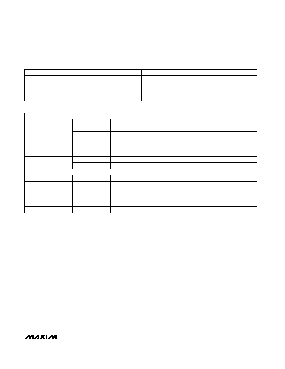
CONTROL MODES
Shutdown
Device in shutdown mode
Standby
Device in standby mode
Transmit
Device in transmit mode
Operating Mode
Receive
Device in receive mode
High gain
Receive LNA in high-gain mode
LNA Gain
Low gain
Receive LNA in low-gain mode
Enable
Sets receive highpass corner frequency to 1kHz
RX_1K
Disable
Sets receive highpass corner frequency to 10kHz
PROGRAM MODES
LO Frequency
Variable
Sets LO frequency from 2400MHz to 2499MHz
22MHz
Sets PLL to work with 22MHz crystal oscillator
Ref Frequency
44MHz
Sets PLL to work with 44MHz crystal oscillator
CP Current
Variable
Sets charge-pump current between 1mA and 2mA
Power Amp Bias
Variable
Sets external power amplifier bias current
Receive LPF BW
Variable
Sets receive lowpass corner frequency from 6.0MHz to 8.5MHz
Table 1. MAX2820/MAX2821 Control Settings
4) Verify that the LO frequency is set to 2437MHz
through the control software.
5) Set the operating mode to "Receive" through the
control software.
6) Measure the power of the 900kHz output tone on the
spectrum analyzer display. Adjust RX_AGC (R2)
between 0V and 2.0V to obtain a baseband output
of -2dBm.
Transmit Mode
To evaluate the MAX2820/MAX2821 in transmit mode:
1) Connect a signal source to TX_BBI (J6). Set the sig-
nal source frequency to 900kHz with an amplitude
of 400mV
P-P
(-4dBm).
2) Connect TX_RF (J1) to the spectrum analyzer. Set
the spectrum analyzer to a center frequency of
2437MHz with a 20MHz span.
3) Verify that the LO frequency is set to 2437MHz
through the control software.
4) Temporarily disable the baseband signal source
output. Set the operating mode to "Transmit"
through the control software. Enable the baseband
signal source output.
5) Measure the amplitude of the upper sideband at
2437.9MHz using the spectrum analyzer. Adjust
TX_GC (R1) to 0V to obtain the maximum RF output.
6) The observed output power should be roughly
-5dBm due to driving only the I channel.
Layout Considerations
The MAX2820/MAX2821 EV kits can serve as guides
for board layout. Keep PC board trace lengths as short
as possible to minimize parasitic inductance. Also,
keep decoupling capacitors as close to the IC as pos-
sible with a direct connection to the ground plane.
Evaluate: MAX2820/MAX2821
MAX2820/MAX2821 Evaluation Kits
4
_______________________________________________________________________________________
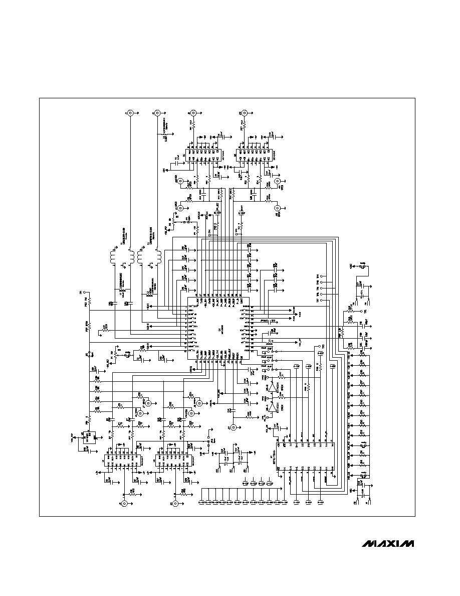
Figure 1. MAX2820/MAX2821 EV Kits Schematic
Evaluate: MAX2820/MAX2821
MAX2820/MAX2821 Evaluation Kits
_______________________________________________________________________________________
5
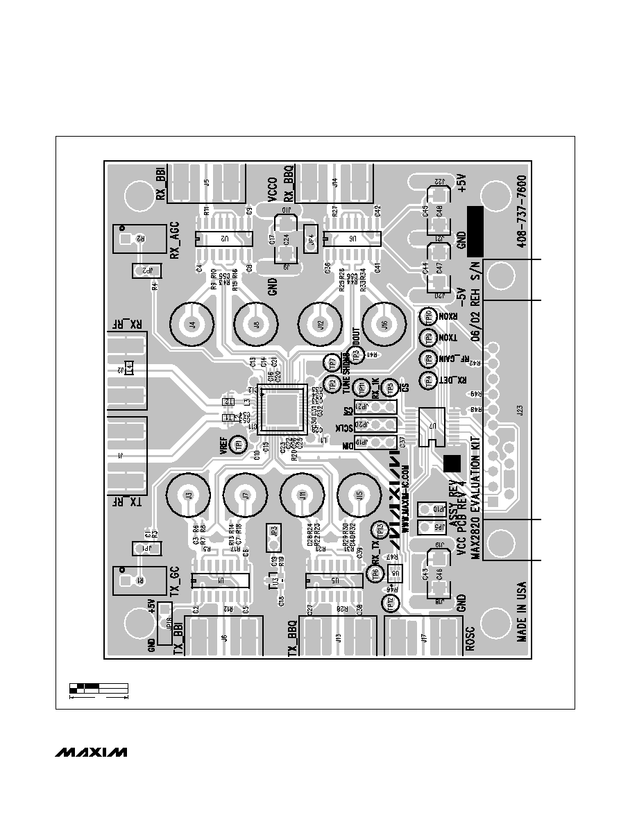
Figure 2. MAX2820/MAX2821 EV Kits PC Board Layout--Top Silkscreen
1.0"