 | –≠–ª–µ–∫—Ç—Ä–æ–Ω–Ω—ã–π –∫–æ–º–ø–æ–Ω–µ–Ω—Ç: MAX3320A | –°–∫–∞—á–∞—Ç—å:  PDF PDF  ZIP ZIP |

_______________General Description
The MAX3320 combines a microprocessor (µP) super-
visory circuit with an RS-232 transceiver. The power-on
reset performs a single function: it asserts a reset signal
whenever the V
CC
supply voltage declines below a pre-
set threshold, staying asserted for at least 100ms after
V
CC
rises above the reset threshold. The MAX3320 has
an active-low RESET output, which is guaranteed to be in
the correct state for V
CC
down to 1V. The reset compara-
tor is designed to ignore fast transients on V
CC
. Reset
thresholds suitable for operation with a variety of supply
voltages are available.
The MAX3320 transceivers have a proprietary low-
dropout transmitter output stage, enabling true RS-232
performance with a dual charge pump powered from a
+3V to +5.5V supply. The device requires only four
small 0.1µF external charge-pump capacitors, and is
guaranteed to run at data rates of up to 250kbps. It
comes in the space-saving 20-pin SSOP package.
________________________Applications
Palmtop Computers
Portable/Battery-Powered Equipment
Hand-Held Equipment
Peripherals
Printers
____________________________Features
o
Precise Monitoring of 5V and 3.3V Power-
Supply Voltages:
-- 100ms (min) Power-On
RESET
Pulse Width
-- Power-Supply Transient Immunity
-- Guaranteed
RESET
Valid to V
CC
= 1V
o
4µA Supply Current Achieved with
AutoShutdown Plus
o
Receivers Always Active
o
Power-On Reset Always Active
o
4µA Low-Power Shutdown
o
250kbps Guaranteed Data Rate
MAX3320A/B/L/T
3V to 5.5V, up to 250kbps True RS-232 Transceiver
with 4µA AutoShutdown Plus and Power-On Reset
________________________________________________________________
Maxim Integrated Products
1
20
19
18
17
16
15
14
13
1
2
3
4
5
6
7
8
C1+
V
CC
C1-
GND
V-
C2-
C2+
V+
TOP VIEW
T1OUT
T2OUT
R1IN
R2IN
R2OUT
R1OUT
T2IN
T1IN
12
11
9
10
FORCEON
FORCEOFF
RESET
INVALID
MAXxxx
SSOP
MAX3320
__________________Pin Configuration
19-1253; Rev 0; 8/97
PART*
MAX3320
_
CAP
MAX3320_EAP
-40∞C to +85∞C
0∞C to +70∞C
TEMP. RANGE
PIN-PACKAGE
20 SSOP
20 SSOP
______________Ordering Information
*
This part offers a choice of reset threshold voltage. From the
table below, select the suffix corresponding to the desired
threshold and insert it into the blank to complete the part
number.
AutoShutdown Plus is a trademark of Maxim Integrated Products.
SUFFIX
A
B
RESET THRESHOLD
(V)
4.25
2.85
L
4.63
T
3.08
Typical Operating Circuit appears at end of data sheet.
For free samples & the latest literature: http://www.maxim-ic.com, or phone 1-800-998-8800.
For small orders, phone 408-737-7600 ext. 3468.
MAX3320A/B/L/T
3V to 5.5V, up to 250kbps True RS-232 Transceiver
with 4µA AutoShutdown Plus and Power-On Reset
2
_______________________________________________________________________________________
ABSOLUTE MAXIMUM RATINGS
ELECTRICAL CHARACTERISTICS
(V
CC
= 3V to 5.5V, C1≠C4 = 0.1µF (tested at 3.3V ±10%), C1 = 0.047µF, C2≠C4 = 0.33µF (tested at 5V ±10%), T
A
= T
MIN
to T
MAX
,
unless otherwise noted. Typical values are at T
A
= +25∞C.)
Stresses beyond those listed under "Absolute Maximum Ratings" may cause permanent damage to the device. These are stress ratings only, and functional
operation of the device at these or any other conditions beyond those indicated in the operational sections of the specifications is not implied. Exposure to
absolute maximum rating conditions for extended periods may affect device reliability.
V
CC
.............................................................................-0.3V to 6V
V+ (Note 1) .................................................................-0.3V to 7V
V- (Note 1)...................................................................0.3V to -7V
V+ +
|
V-
|
(Note 1) ...................................................................13V
Input Voltages
T_IN, FORCEOFF, FORCEON ................................-0.3V to 6V
R_IN.................................................................................±25V
Output Voltages
T_OUT ..........................................................................±13.2V
R_OUT, INVALID, RESET.......................-0.3V to (V
CC
+ 0.3V)
Short-Circuit Duration
T_OUT....................................................................Continuous
Continuous Power Dissipation (T
A
= +70∞C)
SSOP (derate 8.00mW/∞C above +70∞C) ....................640mW
Operating Temperature Ranges
MAX3320_CAP ...................................................0∞C to +70∞C
MAX3320_EAP ................................................-40∞C to +85∞C
Storage Temperature Range .............................-65∞C to +160∞C
Lead Temperature (soldering, 10sec) .............................+300∞C
V
-0.3
0.3
Figure 3
Receiver Input Threshold to
INVALID Output Low
-2.7
Figure 3, negative threshold
V
2.7
Figure 3, positive threshold
Receiver Input Threshold to
INVALID Output High
k
3
5
7
T
A
= +25∞C
Input Resistance
V
0.3
Input Hysteresis
1.8
2.4
V
CC
= 5V
V
1.5
2.4
V
CC
= 3.3V
Input Threshold High
0.8
1.5
V
CC
= 5V
V
0.6
1.2
V
CC
= 3.3V
Input Threshold Low
V
-25
25
Input Voltage Range
µA
4.0
10
FORCEOFF = GND, T
A
= +25∞C
Shutdown Supply Current
mA
0.45
1.0
No load, V
CC
= 3.3V or 5V, T
A
= +25∞C
Power-Supply Current
V
V
CC
-
V
CC -
0.6
0.1
I
OUT
= -1mA
Output Voltage High
V
0.4
I
OUT
= 1.6mA
Output Voltage Low
mV
250
T_IN, FORCEON, FORCEOFF
Input Hysteresis
µA
±0.01
±1.0
T_IN, FORCEON, FORCEOFF
Input Leakage Current
µA
4.0
10
All R_IN unconnected, FORCEON = GND,
FORCEOFF = V
CC
, all T_IN = V
CC
or GND, T
A
= +25∞C
AutoShutdown Plus
Supply Current
V
0.8
T_IN, FORCEON, FORCEOFF
Input Logic Threshold Low
V
2.0
Input Logic Threshold High
UNITS
MIN
TYP
MAX
CONDITIONS
PARAMETER
T_IN, FORCEON,
FORCEOFF
2.4
V
0.4
I
OUT
= 1.6mA
INVALID Output Voltage Low
Note 1:
V+ and V- can have a magnitude of +7V (max), but their absolute difference cannot exceed +13V.
V
CC
= 3.3V
V
CC
= 5V
DC CHARACTERISTICS
LOGIC INPUTS AND RECEIVER OUTPUTS
RECEIVER INPUTS
INVALID
OUTPUT

MAX3320A/B/L/T
3V to 5.5V, up to 250kbps True RS-232 Transceiver
with 4µA AutoShutdown Plus and Power-On Reset
_______________________________________________________________________________________
3
sec
15
30
60
Figure 3
Receiver or Transmitter Edge
to Shutdown
µs
25
Figure 5
Receiver or Transmitter Edge
to Transmitters Enabled
90
µs
Figure 3
Receiver Positive or Negative
Threshold to INVALID Low
µs
0.1
Figure 3
Receiver Positive or Negative
Threshold to INVALID High
UNITS
MIN
TYP
MAX
CONDITIONS
PARAMETER
ELECTRICAL CHARACTERISTICS (continued)
(V
CC
= 3V to 5.5V, C1≠C4 = 0.1µF (tested at 3.3V ±10%), C1 = 0.047µF, C2≠C4 = 0.33µF (tested at 5V ±10%), T
A
= T
MIN
to T
MAX
,
unless otherwise noted. Typical values are at T
A
= +25∞C.)
V
±5.0
±5.4
All transmitter outputs loaded with 3k
to ground
Output Voltage Swing
300
10M
V
CC
= V+ = V- = GND, V
T_OUT
= ±2V
Output Resistance
mA
±35
±60
T_OUT = GND, T_IN = V
CC
or GND
Output Short-Circuit Current
µA
±25
V
T_OUT
= ±12V, V
CC
= 0 to 5.5V, transmitters disabled
Output Leakage Current
V
1.0
5.5
MAX3320_C
RESET Operating Voltage
Range
1.2
5.5
MAX3320_E
V
4.00
4.25
4.50
MAX3320A
RESET Threshold
2.70
2.85
3.00
MAX3320B
4.50
4.63
4.75
MAX3320L
3.00
3.08
3.15
MAX3320T
V
0.3
I
SINK
= 1.2mA, V
CC
= reset threshold, MAX3320B/T
RESET Output Voltage
0.4
I
SINK
= 3.2mA, V
CC
= reset threshold, MAX3320A/L
0.3
I
SINK
= 50µA, V
CC
> 1V, MAX3320_C
0.4
I
SINK
= 100µA, V
CC
> 1.2V, MAX3320_E
V
V
CC
- 0.6
I
OUT
= -1mA
INVALID Output Voltage High
AUTOSHUTDOWN PLUS (FORCEON = GND,
FORCEOFF
= V
CC
)
TRANSMITTER OUTPUTS
RESET
OUTPUT

MAX3320A/B/L/T
3V to 5.5V, up to 250kbps True RS-232 Transceiver
with 4µA AutoShutdown Plus and Power-On Reset
4
_______________________________________________________________________________________
-7.5
V
T_OUT-
V
T_OUT+
-2.5
-5.0
2.5
0
5.0
7.5
0
2000
1000
3000
4000
5000
TRANSMITTER OUTPUT VOLTAGE
vs. LOAD CAPACITANCE
MAX3320 TOC01
LOAD CAPACITANCE (pF)
OUTPUT VOLTAGE (V)
ONE TRANSMITTER AT 250kbps
ONE TRANSMITTER AT 15.6kbps
LOAD = 3k
+ C
L
0
2
8
6
4
10
12
0
2000
1000
3000
4000
5000
SLEW RATE
vs. LOAD CAPACITANCE
MAX3320 TOC02
LOAD CAPACITANCE (pF)
SLEW RATE (V/us)
ONE TRANSMITTER AT 250kbps
ONE TRANSMITTER AT 15.6kbps
LOAD = 3k
+ C
L
NEGATIVE
SLEW
POSITIVE
SLEW
0
250kbps
120kbps
20kbps
10
5
30
20
25
15
40
35
45
0
2000
1000
3000
4000
5000
SUPPLY CURRENT
vs. LOAD CAPACITANCE WHEN
TRANSMITTING DATA
MAX3320 TOC03
LOAD CAPACITANCE (pF)
SUPPLY CURRENT (mA)
ONE TRANSMITTER AT
FULL DATA RATE INDICATED
ONE TRANSMITTER AT
1/16 DATA RATE INDICATED
TIMING CHARACTERISTICS
(V
CC
= 3V to 5.5V, C1≠C4 = 0.1µF, C1≠C4 = 0.1µF (for 3.3V ±10%), C1 = 0.047µF, C2≠C4 = 0.33µF (tested at 5V ±10%),
T
A
= T
MIN
to T
MAX
, unless otherwise noted. Typical values are at T
A
= +25∞C.)
kbps
250
R
L
= 3k
, C
L
= 1000pF, one transmitter switching
Maximum Data Rate
ns
100
|
t
PHL
- t
PLH
|
Transmitter Skew
0.3
µs
0.3
R_IN to R_OUT, C
L
= 150pF
Receiver Propagation Delay
UNITS
MIN
TYP
MAX
CONDITIONS
PARAMETER
t
PLH
t
PHL
ns
200
|
t
PHL
- t
PLH
|
Receiver Skew
C
L
= 150pF to
1000pf
V/µs
6
30
V
CC
= 3.3V, R
L
= 3k
to 7k
,
measured from +3V to -3V or -3V to
+3V, T
A
= +25∞C
Transition-Region Slew Rate
ms
100
280
V
CC
= reset threshold
RESET Active Timeout Period
µs
40
100mV overdrive from reset threshold
V
CC
to RESET Delay
C
L
= 150pF to
2500pf
4
30
__________________________________________Typical Operating Characteristics
(V
CC
= 3.3V, 250kbps data rate, C1≠C4 = 0.1µF, all transmitters loaded with 3k
. Typical values are at T
A
= +25∞C, unless
otherwise noted.)
MAX3320A/B/L/T
3V to 5.5V, up to 250kbps True RS-232 Transceiver
with 4µA AutoShutdown Plus and Power-On Reset
_______________________________________________________________________________________
5
______________________________________________________________Pin Description
300
0
10
100
1000
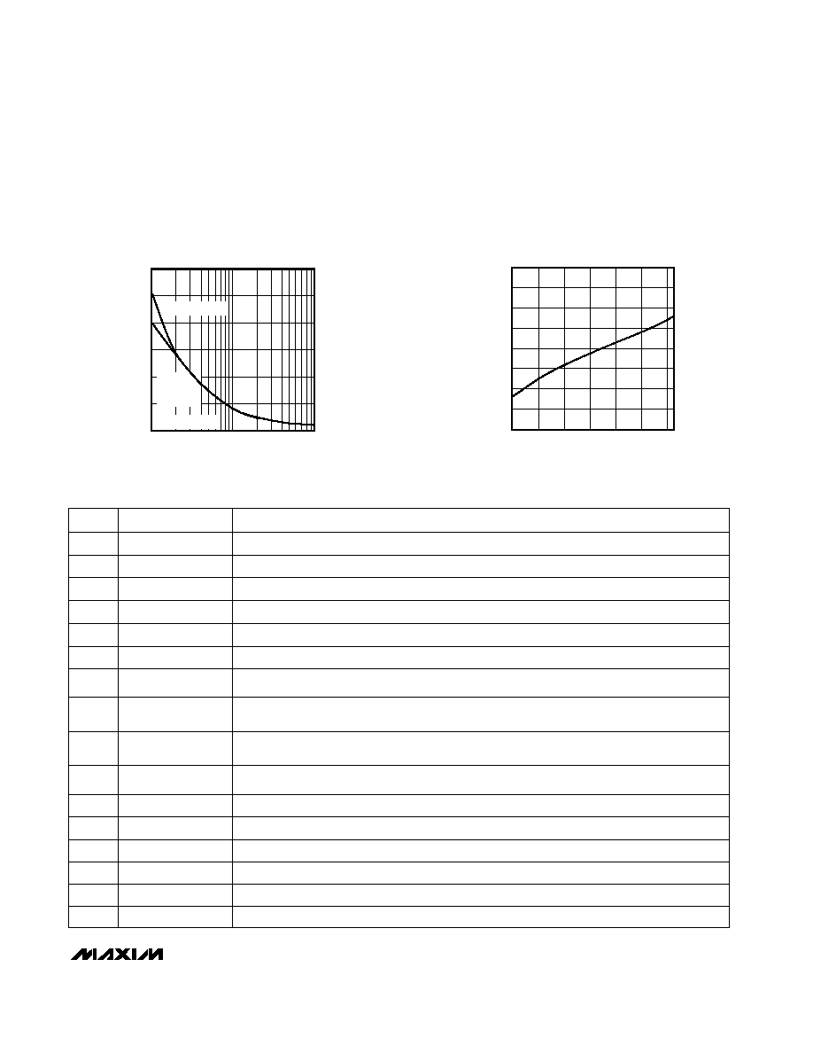
MAXIMUM TRANSIENT DURATION
vs. RESET COMPARATOR OVERDRIVE
50
MAX3320toc05
RESET COMPARATOR OVERDRIVE (mV)
MAXIMUM TRANSIENT DURATION (µs)
100
200
150
250
NOT IN
SHUTDOWN
MODE
SHUTDOWN MODE
C
BYPASS
= 0.1
µ
F
0.960
0.970
1.010
1.000
0.990
0.980
1.030
1.020
1.040
-40
0
-20
20
40
80
60
NORMALIZED POWER-UP RESET
DELAY vs. TEMPERATURE
MAX3320 TOC06
TEMPERATURE (∞C)
POWER-UP RESET DELAY
____________________________Typical Operating Characteristics (continued)
(V
CC
= 3.3V, 250kbps data rate, C1≠C4 = 0.1µF, all transmitters loaded with 3k
. Typical values are at T
A
= +25∞C, unless
otherwise noted.)
20
C1+
Positive terminal of voltage-doubler charge-pump capacitor
19
V
CC
+3V to +5.5V Supply Voltage
18
C1-
Negative terminal of voltage-doubler charge-pump capacitor
NAME
FUNCTION
1
V+
5.5V generated by the charge pump
2
C2+
Positive terminal of inverting charge-pump capacitor
PIN
3
C2-
Negative terminal of inverting charge-pump capacitor
4
V-
-5.5V generated by the charge pump
10
RESET
RESET Output. RESET remains low while V
CC
is below the reset threshold, and for 280ms (max)
after V
CC
rises above the reset threshold.
9
INVALID
Output of the Valid Signal Detector. Asserts when no valid RS-232 levels are present on any of
the receiver inputs for 90µs.
7, 8
R_OUT
TTL/CMOS Receiver Outputs (R1OUT and R2OUT)
5, 6
T_IN
TTL/CMOS Transmitter Inputs (T1IN and T2IN)
17
GND
Ground
15, 16
T_OUT
RS-232 Transmitter Outputs (T2OUT and T1OUT)
13, 14
R_IN
RS-232 Receiver Inputs (R2IN and R1IN)
12
FORCEON
Force-On Input. Drive FORCEON high to override AutoShutdown Plus, keeping transmitters on
(FORCEOFF must be high) (Table 1).
11
FORCEOFF
Force-Off Input. Drive FORCEOFF low to shut down transmitters and on-board power supply.
This overrides AutoShutdown Plus and FORCEON (Table 1).