 | –≠–ª–µ–∫—Ç—Ä–æ–Ω–Ω—ã–π –∫–æ–º–ø–æ–Ω–µ–Ω—Ç: MAX3517 | –°–∫–∞—á–∞—Ç—å:  PDF PDF  ZIP ZIP |
General Description
The MAX3514/MAX3516/MAX3517 programmable-gain
amplifiers are designed for use in CATV upstream
applications. The MAX3514/MAX3517 drive up to
+61dBmV (QPSK) into a 75
load when driven with a
+34dBmV nominal input signal. The MAX3516 drives
up to +64dBmV (QPSK). Both input and output ports
are differential, requiring that an external balun be used
at the output port. The variable gain feature provides
greater than 56dB of dynamic range, which is con-
trolled by an SPITM 3-wire interface. Gain control is
available in 0.5dB steps. The devices operate over a
frequency range of 5MHz to 65MHz.
The MAX3514 is a pin-for-pin compatible upgrade for
the MAX3510. Like the MAX3510, the MAX3514 is inter-
nally matched for use with a 2:1 (voltage ratio) balun.
The MAX3517 utilizes an external output resistor for
greater load-matching flexibility, and offers the same
performance as the MAX3514. The MAX3516 is a high-
er power version of the MAX3514 with 3dB more gain
and output power capability, and is offered in a smaller
thermally enhanced TSSOP-EP package.
These devices operate from a single +5VDC supply and
draw 120mA during transmit (100% duty cycle,
+61dBmV out). The MAX3516 can be operated at up to
+9VDC supply for improved harmonic distortion perfor-
mance. The bias current is automatically adjusted based
on the output level to increase efficiency. Additionally,
the devices are shut off between bursts to minimize
noise and save power while still maintaining a match at
the output port. Shutdown mode disables all circuitry and
reduces current consumption to 10µA (typ).
The MAX3514/MAX3517 are available in a 20-pin QSOP
package and the MAX3516 is available in a 20-pin
TSSOP-EP package. All devices operate in the extend-
ed industrial temperature range (-40∞C to +85∞C).
________________________Applications
DOCSIS
/EuroDOCSIS and DVB Cable
Modems
OpenCable
Set-Top Box
Telephony over Cable
CATV Status Monitor
Features
o Accurate Gain Control
o Gain Programmable in 0.5dB Steps
o 56dB of Gain Control Range
o -55dBc Harmonic Distortion at 65MHz Input
o Low Burst On/Off Transient
o High Efficiency:
35mA at +34dBmV Out
8mA Transmit Disable Mode
MAX3514/MAX3516/MAX3517
Upstream CATV Amplifiers
________________________________________________________________ Maxim Integrated Products
1
20
19
18
17
16
15
14
13
1
2
3
4
5
6
7
8
GND
V
CC
TXEN
N.C.
GND
GND
V
CC
GND
TOP VIEW
OUT+
OUT-
CEXT (N.C.)
N.C.
CS
GND
IN-
IN+
12
11
9
10
SHDN
GND
SCLK
SDA
QSOP/TSSOP-EP
MAX3514
MAX3516
MAX3517
EXPOSED
PADDLE*
( ) FOR MAX3517 ONLY
* MAX3516 ONLY
Pin Configuration
19-1826; Rev 2; 9/01
EVALUATION KIT
AVAILABLE
Ordering Information
SPI is a trademark of Motorola Corp.
DOCSIS/EuroDOCSIS/OpenCable are trademarks of
CableLabs.
PART
TEMP RANGE
PIN-
PACKAGE
MAX3514EEP
-40∞C to +85∞C
20 QSOP
MAX3516EUP
-40∞C to +85∞C
20 TSSOP-EP*
MAX3517EEP
-40∞C to +85∞C
20 QSOP
Typical Operating Circuit appears at end of data sheet.
*Exposed paddle
For pricing, delivery, and ordering information, please contact Maxim/Dallas Direct! at
1-888-629-4642, or visit Maxim's website at www.maxim-ic.com.
MAX3514/MAX3516/MAX3517
Upstream CATV Amplifiers
2
_______________________________________________________________________________________
ABSOLUTE MAXIMUM RATINGS
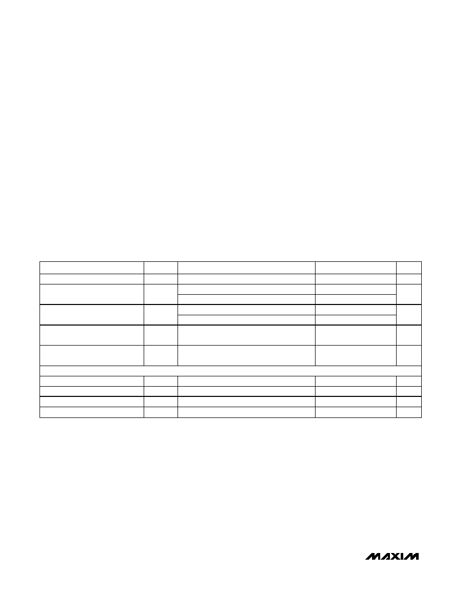
DC ELECTRICAL CHARACTERISTICS--MAX3514/MAX3516/MAX3517
(Typical operating circuit; V
CC
= +4.75V to +5.25V, V
GND
= 0, TXEN = SHDN = high, T
A
= -40∞C to +85∞C. Typical parameters are at
V
CC
= +5V, T
A
= +25∞C, unless otherwise specified.) (Note 1)
Stresses beyond those listed under "Absolute Maximum Ratings" may cause permanent damage to the device. These are stress ratings only, and functional
operation of the device at these or any other conditions beyond those indicated in the operational sections of the specifications is not implied. Exposure to
absolute maximum rating conditions for extended periods may affect device reliability.
V
CC
, OUT+, OUT-................................................-0.3V to +10.0V
Input Voltage Levels (all inputs) .................-0.3V to (V
CC
+ 0.3V)
Continuous Input Voltage (IN+, IN-) ...................................2Vp-p
Continuous Current (OUT+, OUT-) ...................................120mA
Continuous Power Dissipation (T
A
= +70∞C)
20-Pin QSOP (derate 12.3mW/∞C above T
A
= +70∞C). .988mW
20-Pin TSSOP-EP
(derate 27mW/∞C above T
A
= +70∞C) .......................2200mW
Operating Temperature Range .......................... -40∞C to +85∞C
Junction Temperature ..................................................... +150∞C
Storage Temperature Range ............................ -65∞C to +150∞C
Lead Temperature (soldering, 10s) ................................ +300∞C
PARAMETER
SYMBOL
CONDITIONS
MIN
TYP
MAX
UNITS
Supply Voltage
V
CC
4.75
5.25
V
D7 = 1, gain code = 125 (A
V
= 27dB)
120
150
Supply Current Transmit Mode
(MAX3514/MAX3517)
I
CC
D7 = 0, gain code = 100 (A
V
= 0dB)
35
mA
D7 = 1, gain code = 125 (A
V
= 31dB)
160
195
Supply Current Transmit Mode
(MAX3516)
I
CC
D7 = 0, gain code = 94 (A
V
= 0.5dB)
30
mA
Supply Current Transmit Disable
Mode
I
CC
TXEN = low
8
12
mA
Supply Current Low-Power
Standby
I
CC
SHDN = low
10
µA
LOGIC INPUTS
Input High Voltage
V
INH
2.0
V
Input Low Voltage
V
INL
0.8
V
Input High Current
I
BIASH
V
INH
= +3.6V
100
µA
Input Low Current
I
BIASL
V
INL
= 0
-100
µA
MAX3514/MAX3516/MAX3517
Upstream CATV Amplifiers
_______________________________________________________________________________________
3
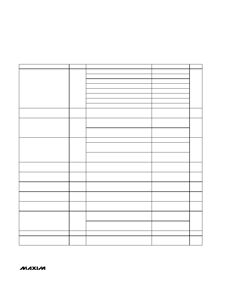
AC ELECTRICAL CHARACTERISTICS--MAX3514
(MAX3514 EV kit; V
CC
= +4.75V to +5.25V, V
GND
= 0, P
IN
= +34dBmV, TXEN = SHDN = high, T
A
= -40∞C to +85∞C. Typical parame-
ters are at V
CC
= +5V, T
A
= +25∞C, unless otherwise specified.) (Note 1)
PARAMETER
SYMBOL
CONDITIONS
MIN
TYP
MAX
UNITS
D7 = 1, gain code = 125, T
A
= 0
∞C to +85∞C
26.7
27.7
28.7
D7 = 1, gain code = 110, T
A
= 0
∞C to +85∞C
19.2
20.2
21.2
D7 = 1, gain code = 87, T
A
= 0
∞C to +85∞C
7.7
8.7
9.7
D7 = 0, gain code = 115, T
A
= 0
∞C to +85∞C
6.7
7.7
8.7
D7 = 0, gain code = 100, T
A
= 0
∞C to +85∞C
-0.8
0.2
1.2
D7 = 0, gain code = 80, T
A
= 0
∞C to +85∞C
-10.8
-9.8
-8.8
D7 = 0, gain code = 60, T
A
= 0
∞C to +85∞C
-20.8
-19.8
-18.8
Voltage Gain, f
IN
= 5MHz
(Note 2)
A
V
D7 = 0, gain code = 48, T
A
= 0
∞C to +85∞C
-27.0
-26.0
-25.0
dB
Voltage Gain, f
IN
= 65MHz
A
V
D7 = 1, gain code = 127, T
A
= -40
∞C to
+85
∞C; Notes 3, 4
26.3
dB
V
OUT
= 61dBmV, f
IN
= 5MHz to 42MHz
(Notes 3, 4)
-0.3
-0.5
Gain Rolloff
V
OUT
= 61dBmV, f
IN
= 5MHz to 65MHz
(Notes 3, 4)
-1.0
-1.5
dB
f
IN
= 5MHz to 65MHz, A
V
= -26dB to +27dB
0.5
f
IN
= 5MHz to 65MHz, A
V
= -26dB to +27dB,
any 2-bit transition of D0, D1
0.7
1
1.3
Gain Step Size
f
IN
= 5MHz to 65MHz, D7 = 0,
gain code = 115; to D7 = 1, gain code = 87
0.7
1.0
1.3
dB
Transmit-Disable Mode Noise
TXEN = low, BW = 160kHz, f
IN
= 5MHz to
65MHz; Note 3
-71
dBmV
Isolation in Transmit-Disable
Mode
TXEN = low, f
IN
= 5MHz to 65MHz (Note 3)
60
dB
Transmit Mode Noise
BW = 160kHz, f
IN
= 5MHz to 65MHz,
A
V
= -26dB to +27dB; Note 3
-59
dBc
Transmit Enable Transient
Duration
TXEN input rise/fall time < 0.1µs, T
A
= +25
∞C
(Note 3)
2
µs
Transmit Disable Transient
Duration
TXEN input rise/fall time < 0.1µs, T
A
= +25
∞C
(Note 3)
2
µs
D7 = 1, gain code = 125 (A
V
= 27dB),
T
A
= +25
∞C
30
100
Transmit Disable/Transmit Enable
Transient Step Size
D7 = 0, gain code = 100 (A
V
= 0.2dB),
T
A
= +25
∞C
1
mVp-p
Input Impedance
Z
IN
f
IN
= 5MHz to 65MHz, single ended; Note 3
1
1.5
k
Output Return Loss
f
IN
= 5MHz to 42MHz in 75
system, D7 = 1
gain code = 125 (A
V
= 27dB) (Note 4)
10
dB

MAX3514/MAX3516/MAX3517
Upstream CATV Amplifiers
4
_______________________________________________________________________________________
PARAMETER
SYMBOL
CONDITIONS
MIN
TYP
MAX
UNITS
Output Return Loss in Transmit-
Disable Mode
f
IN
= 5MHz to 42MHz, in 75
system,
TXEN = low; Note 4
10
dB
Input tones at 42MHz and 42.2MHz, both
+31dBmV, V
OUT
= +58dBmV/tone; Note 3
-53
-47
Two-Tone Third-Order Distortion
IM3
Input tones at 65MHz and 65.2MHz, both
+31dBmV, V
OUT
= +58dBmV/tone
-49
dBc
f
IN
= 33MHz, V
OUT
= +61dBmV; Note 3
-55
-53
2nd-Harmonic Distortion
HD2
f
IN
= 65MHz, V
OUT
= +61dBmV; Note 3
-55
-52
dBc
f
IN
= 22MHz, V
OUT
= +61dBmV
-55
-50.5
3rd-Harmonic Distortion
HD3
f
IN
= 65MHz, V
OUT
= +61dBmV
-55
-50.5
dBc
A
V
= 27dB, V
IN
= +34dBmV to +38dBmV,
f
IN
= 42MHz
0.1
AM to AM
AM/AM
A
V
= 27dB, V
IN
= +34dBmV to +38dBmV,
f
IN
= 65MHz
0.1
dB
A
V
= 27dB, V
IN
= +34dBmV to +38dBmV,
f
IN
= 42MHz
1
AM to PM
AM/PM
A
V
= 27dB, V
IN
= +34dBmV to +38dBmV,
f
IN
= 65MHz
1
degrees
AC ELECTRICAL CHARACTERISTICS--MAX3514 (continued)
(MAX3514 EV kit; V
CC
= +4.75V to +5.25V, V
GND
= 0, P
IN
= +34dBmV, TXEN = SHDN = high, T
A
= -40∞C to +85∞C. Typical parame-
ters are at V
CC
= +5V, T
A
= +25∞C, unless otherwise specified.) (Note 1)

MAX3514/MAX3516/MAX3517
Upstream CATV Amplifiers
_______________________________________________________________________________________
5
AC ELECTRICAL CHARACTERISTICS--MAX3516
(MAX3516 EV kit; V
CC
= +4.75V to +5.25V, V
GND
= 0, P
IN
= +34dBmV, TXEN = SHDN = high, T
A
= -40∞C to +85∞C. Typical parame-
ters are at V
CC
= +5V, T
A
= +25∞C, unless otherwise specified.) (Note 1)
PARAMETER
SYMBOL
CONDITIONS
MIN
TYP
MAX
UNITS
D7 = 1, gain code = 125,
T
A
= 0
∞C to +85∞C
30
31
32
D7 = 1, gain code = 119,
T
A
= 0
∞C to +85∞C
27
28
29
D7 = 1, gain code = 104,
T
A
= 0
∞C to +85∞C
19.5
20.5
21.5
D7 = 1, gain code = 81,
T
A
= 0
∞C to +85∞C
8
9
10
D7 = 0, gain code = 109,
T
A
= 0
∞C to +85∞C
7
8
9
D7 = 0, gain code = 94,
T
A
= 0
∞C to +85∞C
-0.5
0.5
1.5
D7 = 0, gain code = 74,
T
A
= 0
∞C to +85∞C
-10.5
-9.5
-8.5
D7 = 0, gain code = 54,
T
A
= 0
∞C to +85∞C
-20.5
-19.5
-18.5
Voltage Gain, f
IN
= 5MHz
(Note 2)
A
V
D7 = 0, gain code = 42,
T
A
= 0
∞C to +85∞C
-26.5
-25.5
-24.5
dB
Voltage Gain, f
IN
= 65MHz
A
V
D7 = 1, gain code = 127,
T
A
= -40
∞C to +85∞C (Notes 3, 4)
28.1
dB
V
OUT
= 64dBmV,
f
IN
= 5MHz to 42MHz (Notes 3, 4)
-0.3
-0.6
Gain Rolloff
V
OUT
= 64dBmV,
f
IN
= 5MHz to 65MHz (Notes 3, 4)
-1.1
-1.7
dB
f
IN
= 5MHz to 65MHz,
A
V
= -26dB to +30dB
0.5
f
IN
= 5MHz to 65MHz,
A
V
= -26dB to +30dB, any 2-bit
transition of D0, D1
0.7
1.0
1.3
Gain Step Size
f
IN
= 5MHz to 42MHz,
A
V
= -26dB to +30dB,
D7 = 0, gain code = 109; to
D7 = 1, gain code = 81
0.7
1.0
1.3
dB
Transmit-Disable Mode Noise
TXEN = low, BW = 160kHz,
f
IN
= 5MHz to 65MHz
-71
dBmV
Isolation in Transmit-Disable
Mode
TXEN = low, f
IN
= 5MHz to 65MHz
(Note 3)
60
dB
Transmit Mode Noise
BW = 160kHz, f
IN
= 5MHz to 65MHz,
A
V
= -26dB to 27dB (Note 3)
-59
dBc