For free samples & the latest literature: http://www.maxim-ic.com, or phone 1-800-998-8800
_______________General Description
The MAX4106 evaluation kit (EV kit) simplifies evalua-
tion of the MAX4106 high-speed amplifier. The EV kit
circuit demonstrates the MAX4106 in the noninverting
configuration set to a gain of +5V/V. RF-style connec-
tors (SMA) and 75
terminating resistors are included
for video test equipment compatibility.
The EV kit comes with the MAX4106 installed. To evalu-
ate the MAX4107, simply order a free sample
(MAX4107ESA), replace the MAX4106 with the
MAX4107 on the EV board, and change the gain-
setting resistors for the desired gain. The minimum
closed-loop gain for the MAX4107 is +10V/V.
____________________________Features
o
350MHz Bandwidth (A
VCL
= +5V/V)
o
Optional Adjustable Gain
o
Fully Assembled and Tested
Evaluates: MAX4106/MAX4107
MAX4106 Evaluation Kit
________________________________________________________________
Maxim Integrated Products
1
19-0460; Rev 0; 12/95
PART
TEMP. RANGE
BOARD TYPE
MAX4106EVKIT-SO
+25∞C
Surface Mount
QTY
DESCRIPTION
U1
1
C1, C6
2
C2, C5
2
0.1µF, 10% ceramic capacitors
Vitramon VJ1206Y104KXX
C3, C4
2
R1, R2
2
75
, 5% resistors
R
F
1
R
G
1
30
, 5% resistor
IN, OUT
1
SMA connectors
None
1
High-frequency-amplifier PC board
None
1
MAX4106/MAX4107 data sheet
1000pF, 10% ceramic capacitors
Vitramon VJ1206Y102KXX
10µF, 10V, 20% tantalum capacitors
AVX TAJB106M010 or
Sprague 293D106X0010B
Maxim MAX4106ESA
SUPPLIER
PHONE
FAX
AVX
Sprague
Vishay/Vitramon
(803) 946-0690
(603) 224-1961
(203) 268-6261
(803) 626-3123
(603) 224-1430
(203) 452-5670
______________Component Suppliers
DESIGNATION
120
, 5% resistor
____________________Component List
______________Ordering Information
_________________________Quick Start
The MAX4106 EV kit is fully assembled and tested.
Follow these steps to verify board operation.
Do not
turn on the power supply until all connections are
completed.
1) The circuit requires supply voltages of ±5V. Connect
these supplies to the corresponding pads marked
V+ and V-. Connect the power-supply ground to the
pad marked GND.
2) Verify that the J1 shunt is across pins 2 and 3 of the
3-pin jumper J1.
3) Apply a signal no greater than ±0.64V
PK
(4.4dBm)
to the SMA connector marked IN.
4) Connect the output marked OUT to an oscilloscope
through a terminated 75
cable.
5) Turn on the power supply and verify the output sig-
nal on the oscilloscope.
Note: To evaluate the MAX4107, request a MAX4107ESA free
sample.
None
1
Shunt
J1
1
3-pin jumper

Evaluates: MAX4106/MAX4107
MAX4106 Evaluation Kit
2
_______________________________________________________________________________________
MAX4106
U1
R1
75
R2
75
R
G
30
R
F
120
C4
1000pF
SHDN
C5
0.1
µ
F
V+
J1
2
1
3
C3
1000pF
C2
0.1
µ
F
C1
10
µ
F, 10V
C6
10
µ
F, 10V
GND
V-
V+
IN
OUT
CAPACITORS C1, C3, C4, AND C6 ARE OPTIONAL.
1
2
3
4
5
6
7
8
Figure 1. MAX4106 EV Kit Schematic
_______________Detailed Description
Voltage-Gain Adjustment
The MAX4106's gain can be adjusted with the following
minor modifications to the EV board:
1) Referring to Table 1, select the feedback (R
F
) and
gain-setting (R
G
) resistors with the desired gain.
2) Install R
F
and R
G
.
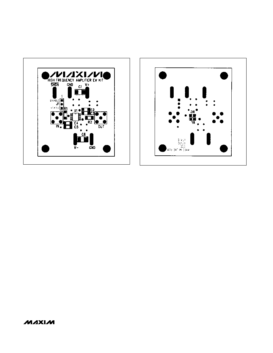
Layout Considerations
The MAX4106 EV kit layout has been optimized for
high-speed signals, with careful attention given to
grounding, power-supply bypassing, and signal-path
layout. The small, surface-mount, ceramic bypass
capacitors C2≠C5 have been placed as close to the
MAX4106 supply pins as possible. The unused pins
have been grounded to prevent unwanted noise from
coupling into the circuit.
Shutdown Control
The MAX4106/MAX4107 EV kit is a standard EV kit
used for many of Maxim's high-speed op amps. As a
result, a shutdown (SHDN) function is incorporated on
the EV kit, but does not apply to the MAX4106/
MAX4107. Because the shutdown control is not applic-
able to the MAX4106/MAX4107, verify that a shunt is
connected to pins 2 and 3 of jumper J1.
Table 1. Gain-Setting Resistors
DEVICE
GAIN
SMALL-SIGNAL
BANDWIDTH
(MHz)
MAX4106
5
350
MAX4107
10
275
R
F
(
)
120
240
R
G
(
)
30
27
MAX4107
20
120
560
30

Maxim cannot assume responsibility for use of any circuitry other than circuitry entirely embodied in a Maxim product. No circuit patent licenses are
implied. Maxim reserves the right to change the circuitry and specifications without notice at any time.
4
___________________Maxim Integrated Products, 120 San Gabriel Drive, Sunnyvale, CA 94086 (408) 737-7600
© 1995 Maxim Integrated Products
Printed USA
is a registered trademark of Maxim Integrated Products.
Evaluates: MAX4106/MAX4107
MAX4106 Evaluation Kit
Figure 4. MAX4106 EV Kit PC Board Layout--Component Side
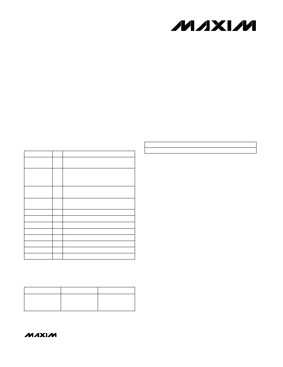
Figure 5. MAX4106 EV Kit PC Board Layout--Solder Side