
General Description
The MAX4273 evaluation kit (EV kit) is a fully assembled
and tested surface-mount hot-swap controller circuit
board that provides current-limiting and DualSpeed/Bi-
LevelTM fault protection. The circuit uses a MAX4273 IC
in a 16-pin QSOP package and is configured for a
+2.7V to +13.2V input voltage range.
The MAX4273 controls the N-channel MOSFET and
provides current regulation during startup. Several con-
figurations allow the MAX4273 IC's unique current regu-
lation architecture to be tailored to the application. The
current-limiting and short-circuit protection features are
configurable and demonstrate the various features pro-
vided by the MAX4273 IC.
The EV kit features a power-on reset (POR) circuit.
Several configurations for autoretry, glitch filters, auxil-
iary V
CC
power, and gate drive speed are provided.
The EV kit can also be reconfigured to emulate the
MAX4271 and MAX4272 hot-swap controllers.
Features
o +2.7V to +13.2V Input Range
o Output Configured for +5V (Configurable from
+2.7V to +13.2V)
o Up to 10A Capability (as Configured)
o Demonstrates Unique Current-Regulation
Architecture
o Auxiliary V
CC
Feature
o Power-On Reset Circuit
o Configurable Autoretry
o Adjustable N-Channel MOSFET Gate Charging
Time
o Configurable Glitch Filters
o Also Emulates MAX4271 and MAX4272 Hot-Swap
Controllers
o Surface-Mount Components
o Fully Assembled and Tested
Evaluates: MAX4273
MAX4273 Evaluation Kit
________________________________________________________________ Maxim Integrated Products
1
19-1944; Rev 0; 1/01
PART
MAX4273EVKIT
0įC to +70įC
TEMP. RANGE
IC PACKAGE
16 QSOP
Ordering Information
DESIGNATION
QTY
DESCRIPTION
C1, C12
2
1.0
ĶF, 16V X5R ceramic
capacitors (0805)
Taiyo Yuden EMK212BJ105KG
C2, C3
2
0.1
ĶF, 50V X7R ceramic
capacitors (0805)
Taiyo Yuden UMK212BJ104KG
C4
1
3300pF, 50V ceramic capacitor
(0603)
Taiyo Yuden UMK107BJ332KZ
C5
1
0.068
ĶF, 50V X7R ceramic
capacitor (0805)
Taiyo Yuden UMK212BJ683KG
C6
1
1000
ĶF, 16V OS-CON capacitor
(H case)
Sanyo 16SA1000M
Component List
DESIGNATION
QTY
DESCRIPTION
C7, C8
0
Not installed (F12 case)
Sanyo 16SV220M
recommended
C9
1
0.22
ĶF, 35V X7R ceramic
capacitor (0805)
Taiyo Yuden GMK212BJ224KG
C10, C13
2
0.01
ĶF, 50V X7R ceramic
capacitors (0603)
Taiyo Yuden UMK107 B103KZ
C11
0
Not installed, (H case)
Sanyo 16SA1000M
recommended
C14
1
330pF, 50V X7R ceramic
capacitor (0603)
Murata GRM39X7R331K050
For price, delivery, and to place orders, please contact Maxim Distribution at 1-888-629-4642,
or visit Maxim's website at www.maxim-ic.com.
DualSpeed/BiLevel is a trademark of Maxim Integrated
Products.

Evaluates: MAX4273
MAX4273 Evaluation Kit
2
_______________________________________________________________________________________
Quick Start
The MAX4273 EV kit is fully assembled and tested.
Follow these steps to verify board operation. Do not
turn on the power supply until all connections are
completed.
MAX4273 Configuration +5V,
10A Output
1) Verify that shunts are on jumpers JU4 (CSPD), JU5
(AUXVCC), and JU7 (CTON).
2) Verify that jumper JU1 (ON) does not have a shunt
installed.
3) Verify that jumper JU3 (RTH) has a shunt installed
on pins 1 and 3.
4) Verify that a shunt is installed on pins 2 and 3 of
jumper JU2 (CTIM) and on pins 1 and 2 of jumper
JU6 (GATE).
5) Utilizing very short 10A rated banana leads
(<6in long), connect the +5VDC power supply to
the V
IN
pad. Utilizing very short 10A rated
banana leads (<6in long), connect the supply
ground to the GND pad.
6) Connect a voltmeter to the V
OUT
and GND pads.
7) Turn on the power supply and verify that the voltage
at V
OUT
is +5V.
8) Test point 1 (TP1) is provided to observe the MOS-
FET gate voltage with an oscilloscope.
Note: The banana leads connecting the power sup-
ply and the load to the EV kit must be very short
(<6in long) and rated for at least 10A of current.
Detailed Description
The MAX4273 EV kit is a hot-swap controller circuit
board that provides configurable current-limiting and
bilevel fault protection for the output. The bilevel fault
protection provides low-amplitude current-overload
protection and protection from instantaneous faults
such as a short-circuit condition. The circuit uses a
MAX4273 IC, configured for an input range of +5V to
+13.2V, and can pass up to 10A of current to the out-
put. The input feeds a current-sense resistor and N-
channel MOSFET, which controls current between the
input and output of the EV kit.
The MAX4273 IC controls the N-channel MOSFET in
conjunction with gate capacitors, which provide current
regulation during startup and bilevel fault protection
during steady-state operation. A jumper to capacitors
and a resistor allow control of the MOSFET gate charg-
ing time. A test point is provided to verify the gate sig-
nal with an oscilloscope.
The MAX4273 EV kit features a POR that will trip when
the input voltage drops by 10%. The autoretry, glitch fil-
ters, and auxiliary Vcc power have jumpers that allow
easy configuration changes. Through proper selection
of jumpers, the EV kit can emulate the MAX4271 and
Note: Please indicate that you are using the MAX4273 when
contacting these component suppliers.
Component Suppliers
SUPPLIER
PHONE
FAX
Dale/Vishay
402-564-3131
402-563-6418
Fairchild
408-822-2000
408-822-2102
International Rectifier
310-322-3331
310-322-3332
IRC
512-992-7900
512-992-3377
Murata
814-237-1431
814-238-0490
Sanyo USA
619-661-6835
619-661-1055
Taiyo Yuden
408-573-4150
408-573-4159
DESIGNATION
QTY
DESCRIPTION
R1, R4, R5
3
1M
Ī5% resistors (0805)
R2, R7
2
10k
Ī1% resistors (0805)
R3
1
0.004
Ī1% 1W power resistor
Dale WSL2512 0.004
Ī1% R86
IRC OARS-1-4m
R6
1
64.9k
Ī1% resistor (0805)
R8
0
Not installed, resistor (0805)
N1
1
30V, 100A N-channel MOSFET
(D
2
PAK)
Fairchild FDB7030L or
International Rectifier IRL3803S
J1≠J4
4
Uninsulated banana jacks
Mouser 530-108-0740-1
JU1, JU4, JU5,
JU7
4
2-pin headers
JU2, JU6
2
3-pin headers
JU3
1
4-pin header
None
7
Shunts (JU1≠JU7)
None
4
Rubber bumpers
3M SJ-5003
U1
1
MAX4273EEE (16-pin QSOP)
None
1
MAX4273 data sheet
None
1
MAX4273 EV kit data sheet
Component List (continued)
Evaluates: MAX4273
MAX4273 Evaluation Kit
_______________________________________________________________________________________
3
MAX4272 hot-swap controllers. PC board pads for
extra output capacitors are provided on the EV kit.
Jumper Selection
Tables 1≠7 display the functions provided by the
MAX4273 EV kit.
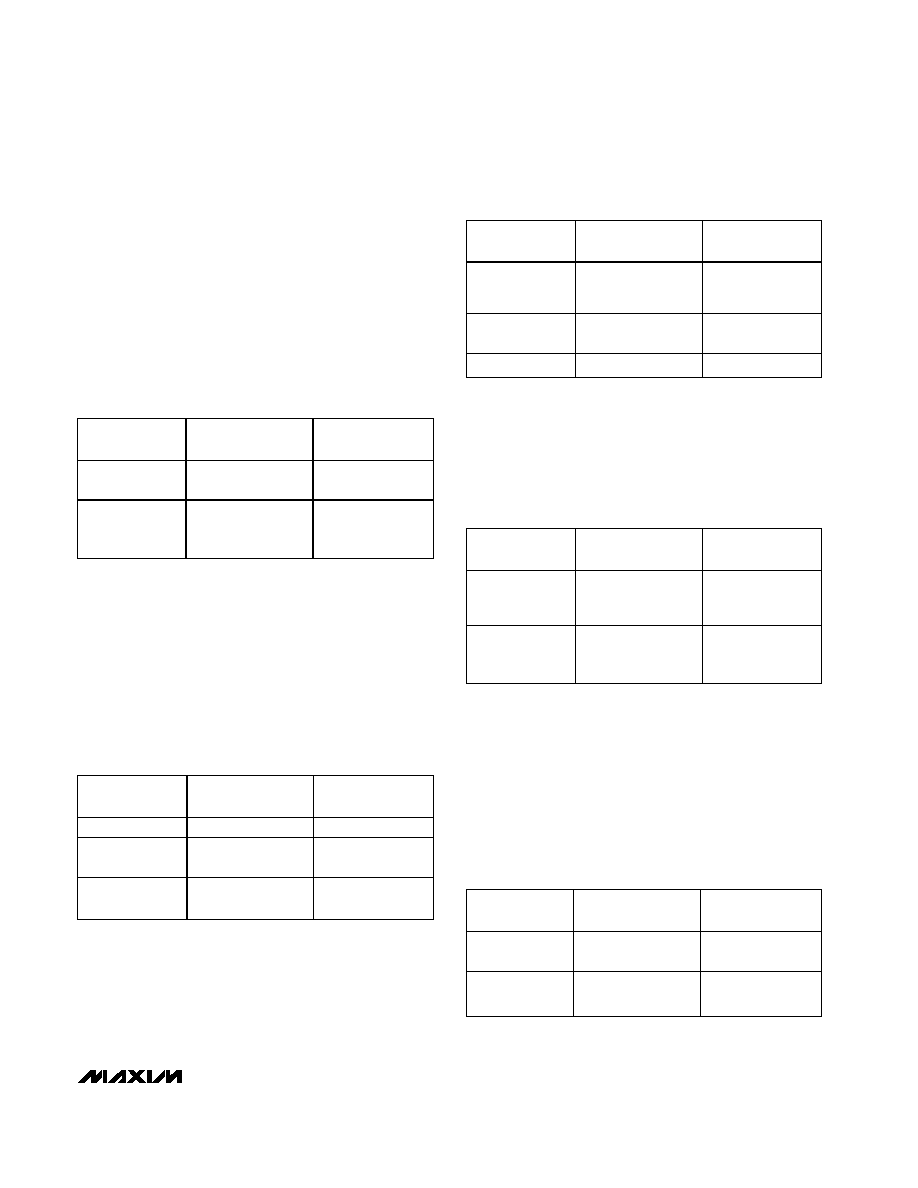
MOSFET Enable and Fault Resetting
The MAX4273 EV kit features a combination shut-
down/unlatch fault mode. The 2-pin jumper, JU1,
selects the shutdown/unlatch mode for the MAX4273
EV kit. Table 1 lists the selectable jumper options.
ON Pin and Latched and Retry Modes
The MAX4273 EV kit features a jumper to select latched
mode or retry timer settings. The 3-pin jumper, JU2,
selects the retry time for the MAX4273 IC. Table 2 lists
the various jumper options.
Fast Comparator and Current Regulation
The MAX4273 EV kit features a jumper to enable or dis-
able the fast comparator and to set the threshold level.
The 3-pin jumper, JU3, selects the threshold level.
Table 3 lists the jumper options.
Slow Comparator Response Time
The MAX4273 EV kit features two choices for the slow
comparator response time. The 2-pin jumper, JU4, is
used to select other speed settings. Table 4 lists the
selectable jumper options.
Auxiliary V
CC
Power
The MAX4273 EV kit features an auxiliary supply for
V
CC
. A capacitor on the auxiliary supply pin provides
energy to the IC during a short-circuit fault condition,
which could cause the main system power supply to
collapse. The 2-pin jumper, JU5, enables or disables
the feature by connecting or disconnecting the capaci-
tor. Table 5 lists the selectable jumper options.
SHUNT
LOCATION
ON PIN
EV KIT OUTPUT
Installed
ON pin pulled low
Disable MOSFET
N1, unlatch fault
None
ON pin pulled high
Enable MOSFET
N1, normal
operation*
Table 1. Jumper JU1 Functions
SHUNT
LOCATION
CTIM PIN
EV KIT MODE
1, 2
Connected to VIN
Latched mode
2, 3
Connected to C3
and C13
Retry mode, 1.1s
None
Connected to C13
Retry mode,
100ms
Table 2. Jumper JU2 Functions
SHUNT
LOCATION
RTH PIN
FAST
COMPARATOR
1, 4
Connected to VIN
Fast comparator
and current
regulation disabled
1, 2
Connected to GND
200mV internal
threshold
1, 3
Connected to R2
100mV threshold
Table 3. Jumper JU3 Functions
SHUNT
LOCATION
CSPD PIN
SLOW
COMPARATOR
Installed
Connected to C2
and C10
22ms slow
comparator
response time
None
Connected to C10
2ms slow
comparator
response time
Table 4. Jumper JU4 Functions
*If JU2 is set for latched mode, the device will be latched
following a fault condition.
SHUNT
LOCATION
AUXVCC PIN
EV KIT MODE
Installed
AUXVCC pin
connected to C1
Auxiliary supply
connected
None
AUXVCC pin
floating
Auxiliary supply
disconnected
Table 5. Jumper JU5 Functions
Evaluates: MAX4273
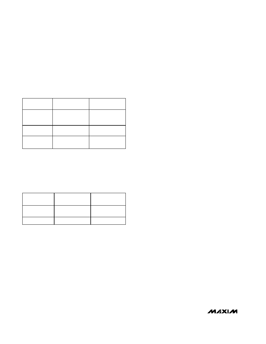
MOSFET Charging Time
The MAX4273 EV kit features several choices for con-
trolling the charging time of the N-channel MOSFET.
Jumper JU6 selects the charge time for the MOSFET.
Table 6 lists the selectable jumper options. The charg-
ing time reflects output voltage close to the final value.
Startup Timer Setting
The MAX4273 EV kit features two choices for the
longest time allowed to completely turn on the MOS-
FET. Jumper JU7 selects the time and Table 7 lists the
selectable jumper options.
Control Modes
MOSFET Gate Control
The MAX4273 EV kit features several options to control
the MOSFET gate charging time. Table 6 lists the vari-
ous jumper selectable options. Resistor R8 is also pro-
vided to prevent MOSFET oscillations when a capacitor
to ground is used. The shorted trace across resistor R8
must be cut open prior to using it. Refer to the
MAX4273 data sheet for information on selecting the
value of resistor R8. Test point TP1 is provided to
observe the gate voltage with an oscilloscope.
Fault Resetting
The MAX4273 EV kit features a jumper (JU1) to
latch/unlatch faults and enable/disable the output MOS-
FET. See Table 1 for proper jumper settings. An exter-
nal controller can be utilized to control the ON pin of
the MAX4273. Refer to the MAX4273 data sheet for
additional functions of the ON pin when toggling it.
Caution: Do not connect an external microcontroller
to the ON pad while a shunt is installed on jumper
JU1. The shunt provides a short from ON to GND
and may damage the external controller.
+3V, 10A Evaluation
The MAX4273 EV kit can evaluate a hot-swap controller
operating at +3V and provide up to 10A of current at
the output. Replace POR resistor R6 with a 34.8k
resistor to obtain a trip level of 2.7V at V
IN
. For other
current levels, resistor R3 must be replaced with a
resistor selected for the desired current. If a different
fast comparator threshold is desired, resistor R2 must
also be replaced. Refer to the MAX4273 data sheet for
information on selecting resistors R2 and R3.
+12V, 2A Evaluation
The MAX4273 EV kit can evaluate a hot-swap controller
operating at +12V and provide up to 2A of current at
the output. Replace POR resistor R6 with a 169k
resistor to obtain a trip level of 10.8V at V
IN
. Resistor R3
must be replaced with a resistor selected for the 2A
load. If a different fast comparator threshold is desired,
resistor R2 must also be replaced. Refer to the
MAX4273 data sheet for information on selecting resis-
tors R2 and R3.
MAX4271/MAX4272 Emulation
The MAX4273 EV kit can emulate the MAX4271 and
MAX4272 IC features. The EV kit uses a MAX4273 IC
and properly set jumpers to emulate a MAX4271 or
MAX4272 design. See Table 8 or 9 to emulate a
MAX4271 or MAX4272 design, respectively. Refer to
the MAX4273 data sheet for a description of specific
pin functions of the MAX4273 IC and its associated
external components. Caution: Only one emulation
mode can be evaluated at a time.
MAX4273 Evaluation Kit
4
_______________________________________________________________________________________
SHUNT
LOCATION
GATE PIN
MOSFET
CHARGE TIME
1, 2
Connected to C5
7ms gate charging
time, fast
discharge possible
2, 3
Connected to C9
22ms gate
charging time
None
Connected to N1
gate terminal only
215
Ķs gate
charging time
Table 6. Jumper JU6 Functions
SHUNT
LOCATION
CTON PIN
EV KIT MODE
Installed
Connected to C4
and C14
1.1ms T
ON
setting
None
Connected to C14
103
Ķs T
ON
setting
Table 7. Jumper JU7 Functions

Evaluates: MAX4273
MAX4273 Evaluation Kit
_______________________________________________________________________________________
5
JUMPER
SHUNT LOCATION
MAX4273 PIN
MAX4271 EV KIT MODE EMULATED
JU1
Installed
ON
Disable MOSFET N1, unlatch fault
JU1
None
ON
Enable MOSFET N1, normal operation
JU2
1, 2
CTIM
No retry, latched mode
JU3
1, 2
RTH
200mV internal fast comparator threshold (50A)
JU4
Installed
CSPD
22ms slow comparator speed setting
JU4
None
CSPD
2ms slow comparator speed setting
JU5
None
AUXVCC
AUXVCC disabled
JU6
2, 3
GATE
22ms MOSFET gate charging time
JU6
None
GATE
215Ķs MOSFET gate charging time
JU7
Installed
CTON
1.1ms startup timer T
ON
setting*
JU7
None
CTON
103Ķs startup timer T
ON
setting*
JU8
Cut open the trace shorting
JU8
LLMON
No line-load monitor feature when emulating a
MAX4271**
Table 8. Emulating a MAX4271 Design
*The MAX4273 CTON pin is providing the CTIM functionality of the MAX4271.
**When demonstrating a MAX4273 EV kit, the PC board trace shorting jumper JU8 must be reinstalled with a wire jumper.
JUMPER
SHUNT LOCATION
MAX4273 PIN
MAX4272 EV KIT MODE EMULATED
JU1
Installed
ON
Disable MOSFET N1
JU1
None
ON
Enable MOSFET N1
JU2
2, 3
CTIM
Retry mode, 1.1s retry time
JU2
None
CTIM
Retry mode, 100ms retry time
JU3
1, 2
RTH
200mV internal fast comparator threshold (50A)
JU4
Installed
CSPD
22ms slow comparator speed setting
JU4
None
CSPD
2ms slow comparator speed setting
JU5
None
AUXVCC
AUXVCC disabled
JU6
2, 3
GATE
22ms MOSFET gate charging time
JU6
None
GATE
215
Ķs MOSFET gate charging time
JU7
Installed
CTON
1.1ms startup timer T
ON
setting*, default
JU7
None
CTON
103
Ķs startup timer T
ON
setting*, default
JU8
Cut open the trace shorting
JU8
LLMON
N o l i ne- l oad m oni tor featur e w hen em ul ati ng a M AX 4272 **
Table 9. Emulating a MAX4272 Design
*The total capacitance on the CTON pin (C4, C14) must equal the total capacitance on the CTIM pin. This will emulate the shared
functionality of a MAX4272 CTIM pin. Refer to the MAX4271/MAX4272/MAX4273 data sheet Table 4 or the Pin Description for more
details on CTIM and CTON.
**When demonstrating a MAX4273 EV kit, the PC board trace shorting jumper JU8 must be reinstalled with a wire jumper.