 | –≠–ª–µ–∫—Ç—Ä–æ–Ω–Ω—ã–π –∫–æ–º–ø–æ–Ω–µ–Ω—Ç: MAX6651 | –°–∫–∞—á–∞—Ç—å:  PDF PDF  ZIP ZIP |
General Description
The MAX6650/MAX6651 fan controllers use an
SMBusTM/I
2
CTM-compatible interface to regulate and mon-
itor the speed of 5VDC/12VDC brushless fans with built-in
tachometers. They automatically force the fan's tachome-
ter frequency (fan speed) to match a preprogrammed
value in the Fan-Speed Register by using an external
MOSFET or bipolar transistor to linearly regulate the volt-
age across the fan. The MAX6650 regulates the speed of
a single fan by monitoring its tachometer output. The
MAX6651 also regulates the speed of a single fan, but it
contains additional tachometer inputs to monitor up to four
fans and control them as a single unit when they are used
in parallel.
The MAX6650/MAX6651 provide general-purpose
input/output (GPIO) pins that serve as digital inputs,
digital outputs, or various hardware interfaces. Capable
of sinking 10mA, these open-drain inputs/outputs can
drive an LED. To add additional hardware control, con-
figure GPIO1 to fully turn on the fan in case of software
failure. To generate an interrupt when a fault condition
is detected, configure GPIO0 to behave as an active-
low alert output. Synchronize multiple devices by set-
ting GPIO2 (MAX6651 only) as an internal clock output
or an external clock input.
The MAX6650 is available in a space-saving 10-pin
µMAX package, and the MAX6651 is available in a
small 16-pin QSOP package.
________________________Applications
RAID
Desktop Computers
Servers
Networking
Workstations
Telecommunications
____________________________Features
o Closed/Open-Loop Fan-Speed Control for
5V/12V Fans
o 2-Wire SMBus/I
2
C-Compatible Interface
o Monitors Tachometer Output
Single Tachometer (MAX6650)
Up to Four Tachometers (MAX6651)
o Programmable Alert Output
o GPIOs
o Hardware Full-On Override
o Synchronize Multiple Fans
o Four Selectable Slave Addresses
o 3V to 5.5V Supply Voltage
o Small Packages
10-Pin µMAX (MAX6650)
16-Pin QSOP (MAX6651)
MAX6650/MAX6651
Fan-Speed Regulators and Monitors
with SMBus/I
2
C-Compatible Interface
________________________________________________________________ Maxim Integrated Products
1
19-1784; Rev 2; 12/01
Ordering Information
10 µMAX
PIN-PACKAGE
TEMP RANGE
-40∞C to +85∞C
MAX6650EUB
PART
16 QSOP
-40∞C to +85∞C
MAX6651EEE
SMBus is a trademark of Intel Corp.
I
2
C is a trademark of Philips Corp.
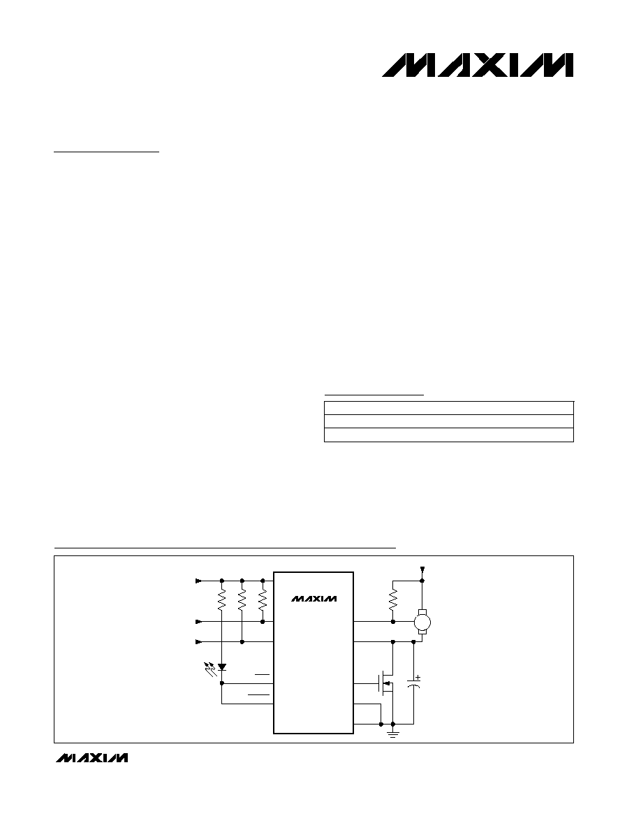
MAX6650
V
CC
SCL
10k
SDA
GPIO0
OUT
ADD
GND
FB
TACH0
V
CC
3V TO 5.5V
V
FAN
5V OR 12V
C
COMP
10
µF
SMBus/I
2
C
INTERFACE
GPIO1
LED
FAN
FULL ON
ALERT
Typical Operating Circuit
Pin Configurations appear at end of data sheet.
For pricing, delivery, and ordering information, please contact Maxim/Dallas Direct! at
1-888-629-4642, or visit Maxim's website at www.maxim-ic.com.
MAX6650/MAX6651
Fan-Speed Regulators and Monitors
with SMBus/I
2
C-Compatible Interface
2
_______________________________________________________________________________________
ABSOLUTE MAXIMUM RATINGS
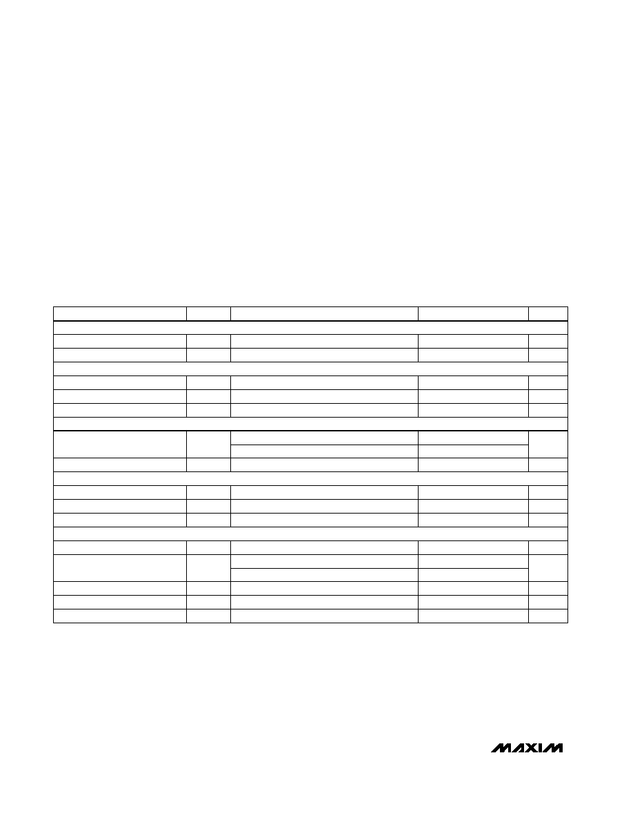
ELECTRICAL CHARACTERISTICS
(V
CC
= 3.0V to 5.5V, T
A
= -40∞C to +85∞C, unless otherwise noted. Typical values are at T
A
= +25∞C and V
CC
= 5V.)
Stresses beyond those listed under "Absolute Maximum Ratings" may cause permanent damage to the device. These are stress ratings only, and functional
operation of the device at these or any other conditions beyond those indicated in the operational sections of the specifications is not implied. Exposure to
absolute maximum rating conditions for extended periods may affect device reliability.
V
CC
to GND ..............................................................-0.3V to +6V
FB, TACH_ ..........................................................-0.3V to +13.2V
All Other Pins..............................................-0.3V to (V
CC
+ 0.3V)
Output Voltages..........................................-0.3V to (V
CC
+ 0.3V)
Maximum Current
Into V
CC
, GND, V
OUT
...................................................100mA
Into All Other Pins ..........................................................50mA
Continuous Power Dissipation (T
A
= +70∞C)
10-Pin µMAX (derate 5.6mW/∞C above +70∞C) ..........444mW
16-Pin QSOP (derate 8.3mW/∞C above +70∞C)..........667mW
Operating Temperature Range ...........................-40∞C to +85∞C
Junction Temperature .....................................................+150∞C
Storage Temperature Range .............................-65∞C to +150∞C
Lead Temperature (soldering, 10s) .................................+300∞C
Input Low Voltage
Input Hysteresis
V
HYS
200
mV
Tachometer Threshold
V
TACH_
V
FB
+ 1.0
V
FB
+3
V
12V fan, 0 < V
FB
< 9V
PARAMETER
SYMBOL
MIN
TYP
MAX
UNITS
Output Source Current
I
SOURCE
50
mA
Output Sink Current
I
SINK
10
mA
Output Voltage Range
V
OUT
0.3
V
CC
- 0.3
V
V
FB
+ 0.5
V
FB
+1.5
Tachometer Input Impedance
R
TACH_
70
100
150
k
Supply Voltage
V
CC
3.0
5.5
V
Supply Current
I
CC
10
mA
DAC Differential Nonlinearity
5
LSB
Useful DAC Resolution
8
bits
Feedback Input Impedance
R
FB
70
100
150
k
Output Sink Current
I
GPIO_
10
mA
CONDITIONS
Guaranteed monotonicity on FB (Note 1)
V
OUT
= V
CC
- 1.8V
Measured at FB (Note 1)
V
OUT
= 0.5V
I
OUT
= ±100µA
5V fan, 0 < V
FB
< 4.5V
0 < VFB < 9V
0 < V
TACH
< 9V
V
GPIO_
= 0.4V
Full-on mode, I
OUT
= 0
V
0.8
V
IL(GPIO_)
Input High Voltage
V
2
V
CC
3.6V
V
IH(GPIO_)
3
V
CC
> 3.6V
Pullup Resistor
R
GPIO_
100
k
TACHOMETER INPUTS (TACH_)
FEEDBACK (FB)
GENERAL-PURPOSE INPUTS/OUTPUTS (GPIO_) (Note 2)
POWER SUPPLY (V
CC
)
OUTPUT (OUT)

MAX6650/MAX6651
Fan-Speed Regulators and Monitors
with SMBus/I
2
C-Compatible Interface
_______________________________________________________________________________________
3
ELECTRICAL CHARACTERISTICS (continued)
(V
CC
= 3.0V to 5.5V, T
A
= -40∞C to +85∞C, unless otherwise noted. Typical values are at T
A
= +25∞C and V
CC
= 5V.)
TIMING CHARACTERISTICS
(V
CC
= 3.0V to 5.5V, T
A
= -40∞C to +85∞C, unless otherwise noted. Typical values are at T
A
= +25∞C and V
CC
= 5V.)
Selects slave address 1001 011 (Table 1)
Selects slave address 1001 000 (Table 1)
Selects slave address 0011 111 (Table 1)
Minimum resistance to GND, selects slave
address 0011 011 (Table 1)
V
ADD
= 0.5V
CONDITIONS
V
V
CC
- 0.05V
V
IH(ADD)
ADD Input High Voltage
V
0.1
V
IL(ADD)
ADD Input Low Voltage
SMBus/I
2
C INTERFACE (SDA, SCL)
k
9.5
10.5
R
ADD
ADD External Pulldown Resistor
to GND
k
5
R
OPEN
Open Resistance
µA
40
80
I
ADD
ADD Pullup Current
UNITS
MIN
TYP
MAX
SYMBOL
PARAMETER
V
SDA
= 0.6V
mA
6
I
SDA
Data Output Sink Current
V
CC
3.6V
V
2
V
0.8
V
IL
Input Low Voltage
0 < V
IN
< V
CC
µA
±1
Input Leakage Current
V
CC
> 3.6V
3
V
IH
Input High Voltage
mV
200
V
HYS
Input Hysteresis
ADDRESS SELECT (ADD)
PARAMETER
SYMBOL
CONDITIONS
MIN
TYP
MAX
UNITS
µs
500
Minimum pulse duration
Glitch Rejection
kHz
254
f
CLK
Clock Frequency
kHz
0
400
f
SCL
SCL Clock Frequency
µs
1.3
t
BUF
Bus Free Time Between Stop
and Start Condition
Hold-Time Start Condition
t
HD:STA
0.6
µs
µs
1.3
t
LOW
Low Period of the SCL Clock
High Period of the SCL Clock
t
HIGH
0.6
µs
µs
0
900
(Note 3)
t
HD:DAT
Data Hold Time
Data Setup Time
t
SU:DAT
100
ns
ns
20 + 0.1C
B
(pf)
300
(Note 4)
t
R
Rise-Time SDA/SCL Signal
(Receiving)
Fall-Time SDA/SCL Signal
(Receiving)
t
F
(Note 4)
20 + 0.1C
B
(pf)
300
ns
ns
20 + 0.1C
B
(pf)
250
I
SINK
< 6mA (Note 4)
t
F
Fall-Time SDA Signal
(Transmitting)
%
-10
+10
V
CC
= 5V
f
CLK
Clock Frequency Uncertainty
TACHOMETERS
GPIO2 (Note 2)
SMBus/I
2
C INTERFACE (Figures 3, 4)

MAX6650/MAX6651
Fan-Speed Regulators and Monitors
with SMBus/I
2
C-Compatible Interface
4
_______________________________________________________________________________________
Typical Operating Characteristics
(T
A
= +25∞C, unless otherwise noted.)
240
245
255
250
260
265
3.0
4.0
3.5
4.5
5.0
5.5
INTERNAL OSCILLATOR FREQUENCY
vs. SUPPLY VOLTAGE
MAX6650/51-01
SUPPLY VOLTAGE (V)
FREQUENCY (kHz)
200
220
260
240
280
300
INTERNAL OSCILLATOR FREQUENCY
vs. TEMPERATURE
MAX6650/51-02
TEMPERATURE (
∞C)
FREQUENCY (kHz)
-50
0
50
100
V
CC
= 5.5V
V
CC
= 3.0V
2.0
2.1
2.3
2.2
2.4
2.5
FEEDBACK VOLTAGE
vs. TEMPERATURE
MAX6650/51-03
TEMPERATURE (
∞C)
FEEDBACK VOLTAGE (V)
-50
0
50
100
1.9
1.8
V
CC
= 5.5V,
V
FAN
= 5.5V, V
FAN
= 12.0V
V
FAN
= 12.0V, V
FAN
= 5.5V
V
CC
= 3.0V
1.80
1.85
1.90
1.95
2.00
2.05
2.10
2.15
2.20
3.0
3.5
4.0
4.5
5.0
5.5
FEEDBACK VOLTAGE vs. SUPPLY
VOLTAGE (DAC SET TO 35)
MAX6650/51-04
SUPPLY VOLTAGE (V)
FEEDBACK VOLTAGE (V)
V
FAN
= 5.5V
V
FAN
= 12.0V
2.0
2.4
2.2
2.8
2.6
3.0
3.2
3.6
3.4
3.8
3.0
3.4
3.8
4.2
4.6
3.2
3.6
4.0
4.4
4.8 5.0
SUPPLY CURRENT
vs. SUPPLY VOLTAGE
MAX6650/51-05
SUPPLY VOLTAGE (V)
SUPPLY CURRENT (mA)
1.5
2.0
3.0
2.5
3.5
4.0
-40
0
-20
20
40
60
80
100
SUPPLY CURRENT vs. TEMPERATURE
MAX6650/51-06
TEMPERATURE (
∞C)
SUPPLY CURRENT (mA)
V
CC
= 5.5V
V
CC
= 3V
TIMING CHARACTERISTICS (continued)
(V
CC
= 3.0V to 5.5V, T
A
= -40∞C to +85∞C, unless otherwise noted. Typical values are at T
A
= +25∞C and V
CC
= 5V.)
Note 1: For proper measurement of V
FB
, connect OUT and FB as shown in the Typical Operating Circuit.
Note 2: GPIO2, GPIO3, and GPIO4 only in the MAX6651.
Note 3: Note that the transition must internally provide at least a hold time to bridge the undefined region (300ns max) of SCL's
falling edge.
Note 4: C
B
is the total capacitance of one bus line in pF. Tested with C
B
= 400pF. Rise and fall times are measured between 0.3 x
V
CC
and 0.7 x V
CC
.
PARAMETER
SYMBOL
CONDITIONS
MIN
TYP
MAX
UNITS
µs
ns
0
50
0.6
t
SPIKE
t
SU:STO
Setup Time for Stop Condition
Pulse Width of Spike Suppressed
MAX6650/MAX6651
Fan-Speed Regulators and Monitors
with SMBus/I
2
C-Compatible Interface
_______________________________________________________________________________________
5
Detailed Description
The MAX6650/MAX6651 use an SMBus/I
2
C-Compatible
interface to regulate and monitor the speed of
5VDC/12VDC brush-less fans with built-in open-collec-
tor/drain tachometers. Regulating fan speed propor-
tionally with temperature saves power, increases fan
life, and reduces acoustic noise. Since fan speed is
proportional to the voltage across the fan, the
MAX6650/MAX6651 control the speed by regulating the
voltage on the low side of the fan with an external MOS-
FET or bipolar transistor.
The MAX6650/MAX6651 each contain two internal con-
trol loops. The first loop controls the voltage across the
fan. The internal digital-to-analog converter (DAC) sets
the reference voltage for an internal amplifier (Figure 1),
which then drives the gate of an external N-channel
MOSFET (or the base of a bipolar transistor) to regulate
the voltage on the low side of the fan. As the reference
voltage provided by the DAC changes, the feedback
amplifier automatically adjusts the feedback voltage,
which changes the voltage across the fan.
The second control loop consists of the internal digital
logic that controls the fan's speed. The MAX6650/
MAX6651 control fan speed by forcing the tachometer
frequency to equal a reference frequency set by the
Fan-Speed Register, the prescaler, and the internal
oscillator (see the Fan-Speed Register section). When
the tachometer frequency is too high, the value of the
DAC's input register is increased by the regulator.
Once the DAC voltage increases, the analog control
loop forces the feedback voltage to rise, which reduces
the voltage across the fan. Since fan speed is propor-
tional to the voltage across the fan, the fan slows down.
2-Wire SMBus/I
2
C-Compatible
Digital Interface
From a software perspective, the MAX6650/MAX6651
appear as a set of byte-wide registers that contain
speed control, tachometer count, alarm conditions, or
configuration bits. These devices use a standard
SMBus/I
2
C-compatible 2-wire serial interface to access
the internal registers.
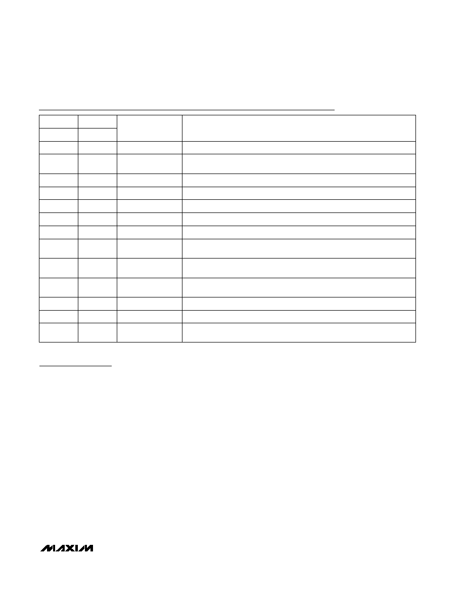
Pin Description
FUNCTION
NAME
PIN
PIN
MAX6650
MAX6651
Tachometer Input. Used to close the loop around the tachometer.
TACH0
1
1
--
2, 3, 16
TACH2, TACH3,
TACH1
Tachometer Inputs. Used to monitor tachometers only.
Ground
GND
4
2
3
5
SDA
2-Wire Serial-Data Input/Output (open drain)
2-Wire Serial Clock Input
SCL
6
4
5
8
ADD
Slave Address Select Input (Table 1)
General-Purpose Input/Output (open drain). Configurable to act either as an out-
put or as an input (FULL ON or general purpose).
General-Purpose Input/Output (open drain). Configurable to act as a general
input/output line or an active-low ALERT output.
General-Purpose Input/Output (open drain). Configurable to act as a general
input/output line, an internal clock output, or an external clock input.
Output. Drives the external MOSFET or bipolar transistor.
+3.0V to +5.5V Power Supply
Feedback Input. Closes the loop around the external MOSFET or bipolar tran-
sistor.
FB
V
CC
OUT
GPIO2
GPIO0
GPIO1
9
6
7
10
11
--
13
8
9
14
15
10
--
7, 12
GPIO4, GPIO3
General-Purpose Input/Output (open drain)