 | –≠–ª–µ–∫—Ç—Ä–æ–Ω–Ω—ã–π –∫–æ–º–ø–æ–Ω–µ–Ω—Ç: MAX690A | –°–∫–∞—á–∞—Ç—å:  PDF PDF  ZIP ZIP |

MAX690A/MAX692A/MAX802L/MAX802M/MAX805L
Microprocessor Supervisory Circuits
________________________________________________________________
Maxim Integrated Products
1
1
2
3
4
8
7
6
5
V
BATT
RESET (RESET)
WDI
PFO
PFI
GND
V
CC
V
OUT
DIP/SO
TOP VIEW
MAX690A
MAX692A
MAX802L
MAX802M
MAX805L
( ) ARE FOR MAX805L ONLY.
_________________Pin Configurations
V
CC
NMI
I/O LINE GND
BUS
V
CC
CMOS
RAM
GND
UNREGULATED DC REGULATED +5V
RESET
PFO
WDI
V
OUT
GND
V
BATT
V
CC
PFI
R
1
R
2
O.1
µ
F
3.6V
LITHIUM
BATTERY
MAX690A
MAX802L
µ
P
RESET
__________Typical Operating Circuit
Call toll free 1-800-998-8800 for free samples or literature.
19-4333; Rev 3; 9/93
__________________General Description
The MAX690A/MAX692A/MAX802L/MAX802M/MAX805L
reduce the complexity and number of components
required for power-supply monitoring and battery-control
functions in microprocessor (µP) systems. They signifi-
cantly improve system reliability and accuracy compared
to separate ICs or discrete components.
These parts provide four functions:
1) A reset output during power-up, power-down, and
brownout conditions.
2) Battery-backup switching for CMOS RAM, CMOS
µP, or other low-power logic.
3) A reset pulse if the optional watchdog timer has not
been toggled within 1.6sec.
4) A 1.25V threshold detector for power-fail warning or
low-battery detection, or to monitor a power supply
other than +5V.
The parts differ in their reset-voltage threshold levels
and reset outputs. The MAX690A/MAX802L/MAX805L
generate a reset pulse when the supply voltage drops
below 4.65V, and the MAX692A/MAX802M generate a
reset below 4.40V. The MAX802L/MAX802M guaran-
tee power-fail accuracies to ±2%. The MAX805L is the
same as the MAX690A except that RESET is provided
instead of
RESET
.
All parts are available in 8-pin DIP and SO packages.
The MAX690A/MAX802L are pin compatible with the
MAX690 and MAX694. The MAX692A/MAX802M are
pin compatible with the MAX692.
_______________________Applications
Battery-Powered Computers and Controllers
Intelligent Instruments
Automotive Systems
Critical µP Power Monitoring
___________________________Features
o
Precision Supply-Voltage Monitor:
4.65V for MAX690A/MAX802L/MAX805L
4.40V for MAX692A/MAX802M
o
Reset Time Delay ≠ 200ms
o
Watchdog Timer ≠ 1.6sec Timeout
o
Battery-Backup Power Switching
o
200µA Quiescent Supply Current
o
50nA Quiescent Supply Current in Battery-
Backup Mode
o
Voltage Monitor for Power-Fail or Low-Battery
Warning
o
Power-Fail Accuracy Guaranteed to ±2%
(MAX802L/M)
o
Guaranteed
RESET
Assertion to V
CC
= 1V
o
8-Pin SO and DIP Packages
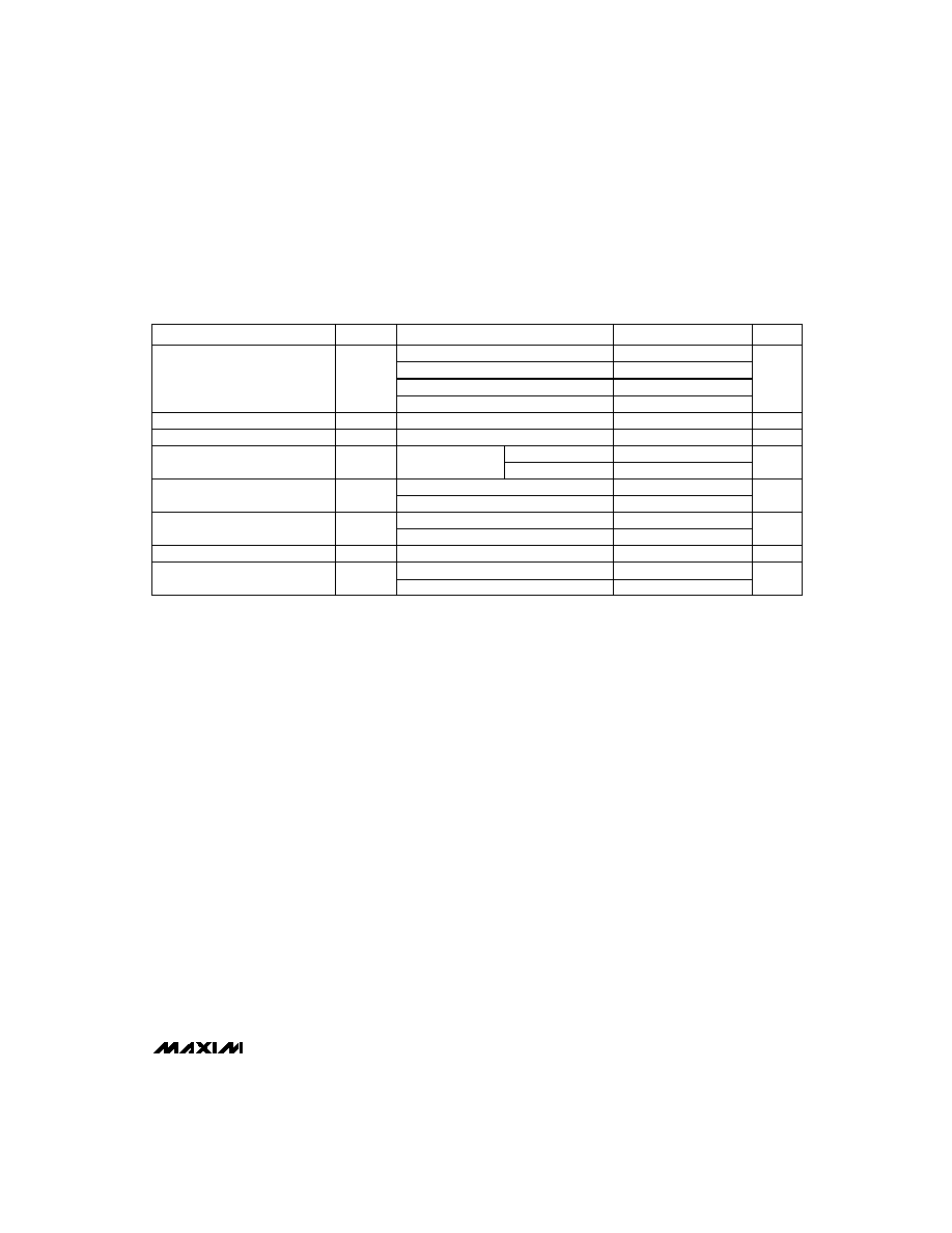
______________Ordering Information
PART
TEMP. RANGE
PIN-PACKAGE
MAX690A
CPA
8 Plastic DIP
MAX690ACSA
0∞C to +70∞C
8 SO
MAX690AC/D
0∞C to +70∞C
Dice*
MAX690AEPA
-40∞C to +85∞C
8 Plastic DIP
MAX690AESA
-40∞C to +85∞C
8 SO
MAX690AMJA
-55∞C to +125∞C
8 CERDIP**
Ordering Information continued on last page.
* Dice are specified at T
A
= +25∞C
**Contact factory for availability and processing to MIL-STD-883.
0∞C to +70∞C

MAX690A/MAX692A/MAX802L/MAX802M/MAX805L
Microprocessor Supervisory Circuits
2
_______________________________________________________________________________________
Terminal Voltage (with respect to GND)
V
CC
. . . . . . . . . . . . . . . . . . . . . . . . . . . . . . . . . . . . . . . . . . . . . . . -0.3V to 6.0V
V
BATT
. . . . . . . . . . . . . . . . . . . . . . . . . . . . . . . . . . . . . . . . . . . . . . -0.3V to 6.0V
All Other Inputs (Note 1) . . . . . . . . . . . . . . . . -0.3V to (V
CC
+ 0.3V)
Input Current
V
CC
. . . . . . . . . . . . . . . . . . . . . . . . . . . . . . . . . . . . . . . . . . . . . . . . . . . . . . 200mA
V
BATT
. . . . . . . . . . . . . . . . . . . . . . . . . . . . . . . . . . . . . . . . . . . . . . . . . . . . . 50mA
GND . . . . . . . . . . . . . . . . . . . . . . . . . . . . . . . . . . . . . . . . . . . . . . . . . . . . . . 20mA
Output Current
V
OUT
. . . . . . . . . . . . . . . . . . . Short-Circuit Protected for up to 10sec
All Other Outputs . . . . . . . . . . . . . . . . . . . . . . . . . . . . . . . . . . . . . . . . 20mA
Rate of Rise, V
CC
, V
BATT
. . . . . . . . . . . . . . . . . . . . . . . . . . . . . . . . 100V/µs
Continuous Power Dissipation
Plastic DIP (derate 9.09mW/∞C above +70∞C) . . . . . . . . 727mW
SO (derate 5.88mW/∞C above +70∞C) . . . . . . . . . . . . . . . . 471mW
CERDIP (derate 8.00mW/∞C above +70∞C) . . . . . . . . . . . 640mW
Operating Temperature Ranges:
MAX69_AC_ _, MAX80_ _ C_ _ . . . . . . . . . . . . . . . . . . 0∞C to +70∞C
MAX69_AE_ _, MAX80_ _ E_ _ . . . . . . . . . . . . . . . . -40∞C to +85∞C
MAX69_AMJA, MAX805LMJA . . . . . . . . . . . . . . . . -55∞C to +125∞C
Storage Temperature Range . . . . . . . . . . . . . . . . . . -65∞C to +160∞C
Lead Temperature (soldering, 10sec) . . . . . . . . . . . . . . . . . . +300∞C
ELECTRICAL CHARACTERISTICS
(V
CC
= 4.75V to 5.5V for MAX690A/MAX802L/MAX805L, V
CC
= 4.5V to 5.5V for MAX692A/MAX802M, V
BATT
= 2.8V,
T
A
= T
MIN
to T
MAX
, unless otherwise noted.)
Stresses beyond those listed under "Absolute Maximum Ratings" may cause permanent damage to the device. These are stress ratings only, and functional
operation of the device at these or any other conditions beyond those indicated in the operational sections of the specifications is not implied. Exposure to
absolute maximum rating conditions for extended periods may affect device reliability.
PARAMETER
SYMBOL
CONDITIONS
MIN
TYP
MAX
UNITS
Operating Voltage Range,
V
CC
, V
BATT
(Note 2)
MAX69_AC, MAX802_C
1.0
5.5
V
MAX805LC
MAX69_AE/M, MAX80_ _E
1.2
5.5
Supply Current (Excluding I
OUT
)
I
SUPPLY
MAX69_AC, MAX802_C
200
350
µA
MAX69_AE/M, MAX802_E, MAX805LE/M
200
500
I
SUPPLY
in Battery-Backup Mode
(Excluding I
OUT
)
V
CC
= 0V,
V
BATT
= 2.8V
0.05
1.0
5.0
5.5V > V
CC
>
V
BATT
+0.2V
-0.1
0.02
µA
-1.0
0.02
V
OUT
Output
I
OUT
= 5mA
V
CC
- 0.05 V
CC
- 0.025
V
ABSOLUTE MAXIMUM RATINGS
Note 1:
The input voltage limits on PFI and WDI may be exceeded if the current into these pins is limited to less than 10mA.
V
BATT
Standby Current (Note 3)
V
CC
- 0.5
V
CC
- 0.25
V
OUT
in Battery-Backup Mode
I
OUT
= 250µA, V
CC
< V
BATT
- 0.2V
V
BATT
- 0.1 V
BATT
- 0.02
V
I
OUT
= 50mA
Battery Switch Threshold, V
CC
to V
BATT
V
CC
< V
RT
20
mV
-20
µA
T
A
= +25∞C
T
A
= +25∞C
T
A
= T
MIN
to T
MAX
Power-up
Power-down
Battery Switchover Hysteresis
40
mV
Reset Threshold
V
RT
MAX690A, MAX802L, MAX805L
V
MAX692A, MAX802M
4.25
4.40
4.50
MAX802L, T
A
= +25∞C, V
CC
falling
4.55
4.70
MAX802M, T
A
= +25∞C, V
CC
falling
4.30
4.45
Reset Threshold Hysteresis
40
mV
Reset Pulse Width
t
RS
140
200
280
ms
RESET
Output Voltage
I
SOURCE
= 800µA
V
CC
- 1.5
V
I
SINK
= 3.2mA
0.4
0.3
0.3
T
A
= T
MIN
to T
MAX
MAX69_AC, MAX802_C, V
CC
= 1.0V
I
SINK
= 50µA
MAX69_AE/M, MAX802_E,
V
CC
= 1.2V, I
SINK
= 100µA
1.1
5.5
4.50
4.65
4.75
V
MAX690A/MAX692A/MAX802L/MAX802M/MAX805L
Microprocessor Supervisory Circuits
_______________________________________________________________________________________
3
PARAMETER
SYMBOL
CONDITIONS
MIN
TYP
MAX
UNITS
RESET Output Voltage
MAX805LC, I
SOURCE
= 4µA, V
CC
= 1.1V
0.8
MAX805LE/M, I
SOURCE
= 4µA, V
CC
= 1.2V
0.9
MAX805L, I
SOURCE
= 800µA
V
CC
- 1.5
MAX805L, I
SINK
= 3.2mA
0.4
Watchdog Timeout
t
WD
1.00
1.60
2.25
sec
PFO
Output Voltage
I
SOURCE
= 800µA
V
CC
- 1.5
V
I
SINK
= 3.2mA
0.4
Note 2:
Either V
CC
or V
BATT
can go to 0V, if the other is greater than 2.0V.
Note 3:
"-" = battery-charging current, "+" = battery-discharging current.
Note 4:
WDI is guaranteed to be in an intermediate, non-logic level state if WDI is floating and V
CC
is in the operating voltage range.
WDI is internally biased to 35% of V
CC
with an input impedance of 50k
.
ELECTRICAL CHARACTERISTICS (continued)
(V
CC
= 4.75V to 5.5V for MAX690A/MAX802L/MAX805L, V
CC
= 4.5V to 5.5V for MAX692A/MAX802M, V
BATT
= 2.8V,
T
A
= T
MIN
to T
MAX
, unless otherwise noted.)
WDI = 0V
-150
-50
V
WDI Input Current
WDI = V
CC
50
150
3.5
µA
WDI Input Threshold (Note 4)
V
CC
= 5V
0.8
V
WDI Pulse Width
t
WP
V
IL
= 0.4V, V
IH
= (0.8) (V
CC
)
50
ns
Logic low
Logic high
MAX69_A, MAX805L, V
CC
= 5V
1.20
1.25
1.30
PFI Input Threshold
MAX802_C/E, V
CC
= 5V
1.225
1.250
1.275
PFI Input Current
-25
0.01
25
nA

MAX690A/MAX692A/MAX802L/MAX802M/MAX805L
Microprocessor Supervisory Circuits
4
_______________________________________________________________________________________
__________________________________________Typical Operating Characteristics
MAX805L
RESET OUTPUT VOLTAGE
vs. SUPPLY VOLTAGE
500ms/div
0V
V
CC
+5V
1V/div
RESET
0V
+5V
1V/div
10k
330
pF
VCC
RESET
GND
VBATT
MAX805L
RESET RESPONSE TIME
2
µ
s/div
0V
V
CC
+4V
0V
+4V
+5V
GND
RESET
V
CC
330pF
10k
4.75
0
OUTPUT VOLTAGE
vs. LOAD CURRENT
4.80
5.00
I
OUT
(mA)
V
OUT
(V)
40
4.90
4.85
10
30
50
4.95
20
V
CC
= +5V
V
BATT
= +2.8V
T
A
= +25∞C
SLOPE = 5
2.70
0
OUTPUT VOLTAGE
vs. LOAD CURRENT
2.72
2.80
I
OUT
(mA)
V
OUT
(V)
0.8
2.76
2.74
0.2
0.6
1.0
2.78
0.4
V
CC
= 0V
V
BATT
= +2.8V
T
A
= +25∞C
SLOPE = 80
MAX690A
RESET OUTPUT VOLTAGE
vs. SUPPLY VOLTAGE
500ms/div
V
CC
0V
RESET
0V
+5V
1V/div
+5V
1V/div
V
CC
GND
RESET
V
CC
2k
RESET
330pF
T
A
= +25∞C
V
BATT
= OV
MAX690A
RESET RESPONSE TIME
2
µ
s/div
V
CC
+5V
RESET
+5V
+4V
1V/div
0V
T
A
= +25∞C
V
CC
GND
RESET
V
CC
10k
RESET
30pF
POWER-FAIL COMPARATOR
RESPONSE TIME
400ns/div
PFI
+1.30V
PFO
+5V
+0V
+1.2V
+5V
PFO
30pF
1k
+1.25V
PFI
V
CC
= +5V
T
A
= +25∞C
POWER-FAIL COMPARATOR
RESPONSE TIME
400ns/div
PFI
+1.20V
PFO
0V
+3V
+1.3V
V
CC
= +5V
T
A
= +25∞C
+5V
PFO
30pF
1k
+1.25V
PFI
MAX690A/MAX692A/MAX802L/MAX802M/MAX805L
Microprocessor Supervisory Circuits
_______________________________________________________________________________________
5
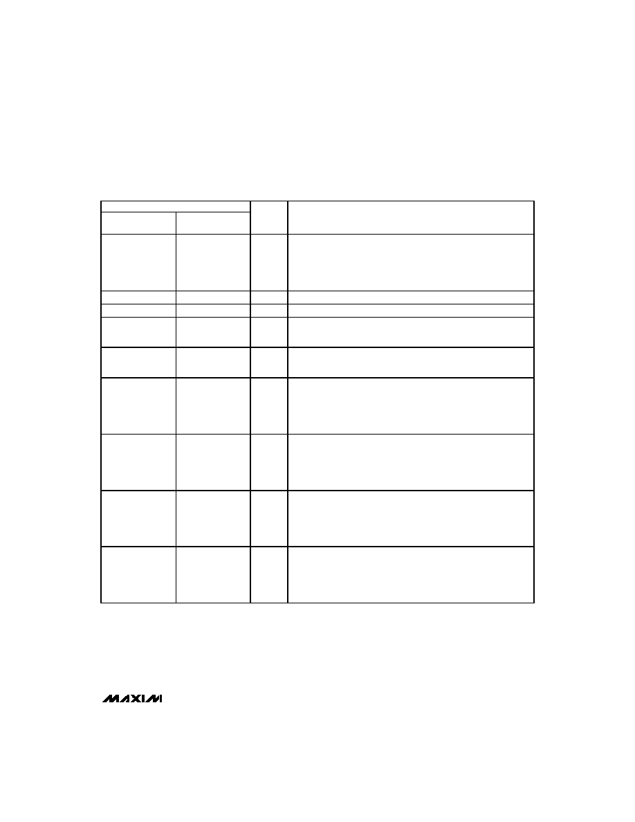
______________________________________________________________Pin Description
NAME
FUNCTION
MAX805L
1
1
V
OUT
2
2
V
CC
+5V Supply Input
3
3
GND
Ground
4
4
PFI
5
5
PFO
6
6
WDI
7
RESET
8
8
V
BATT
Power-Fail Comparator Input. When PFI is less than 1.25V,
PFO
goes
low. Connect PFI to GND or V
CC
when not used.
Power-Fail Output. When PFI is less than 1.25V,
PFO
goes low;
otherwise
PFO
stays high.
Watchdog Input. If WDI remains high or low for 1.6sec, the internal
watchdog timer runs out and reset is triggered. If WDI is left floating or
connected to a high-impedance three-state buffer, the watchdog
feature is disabled. The internal watchdog timer clears whenever reset
is asserted, WDI is three-stated, or WDI sees a rising or falling edge.
PIN
MAX690A/MAX692A
MAX802L/MAX802M
Reset Output. Whenever
RESET
is triggered, it pulses low for 200ms. It
stays low when V
CC
is below the reset threshold (4.65V in the
MAX690A/MAX802L and 4.4V in the MAX692A/MAX802M) and remains
low for 200ms after V
CC
rises above the reset threshold. A watchdog
timeout also triggers
RESET
.
Supply Output for CMOS RAM. When V
CC
is above the reset threshold,
V
OUT
connects to V
CC
through a P-channel MOSFET switch. When V
CC
is below the reset threshold, the higher of V
CC
or V
BATT
will be
connected to V
OUT
.
Backup-Battery Input. When V
CC
falls below the reset threshold, V
BATT
will be switched to V
OUT
if V
BATT
is 20mV greater than V
CC
. When V
CC
rises to 20mV above V
BATT
, V
OUT
will be reconnected to V
CC
. The 40mV
hysteresis prevents repeated switching if V
CC
falls slowly.
≠
7
RESET
Active-High Reset Output is the inverse of
RESET
. When RESET is
asserted, the RESET output voltage = V
CC
or V
BATT
, whichever is
higher.