
General Description
The MAX6951 evaluation kit (EV kit) is an assembled and
tested PC board that demonstrates the MAX6951 serially
interfaced eight-digit LED display driver IC. The EV kit is
powered by a user-supplied +4VDC to +6.5VDC power
supply. A configurable +3.3V or user-configurable low-
dropout (LDO) linear regulated power supply provides
power for the entire EV kit. An SPITM-compatible serial
interface is connected to an IBM PC-compatible com-
puter's parallel port for easy evaluation. The EV kit can
easily be reconfigured for interfacing with a user-sup-
plied microcontroller (standalone operation).
Windows
Æ
95/98-compatible software provides a user-
friendly interface to demonstrate the various features of
the MAX6951 IC. The program is menu driven and
offers a graphic interface with control buttons. Windows
NT/2000 support is available; contact the factory for
details.
Features
o Eight-Digit 7-Segment + dp Common-Cathode
Display
o SPI-Compatible Serial Interface
o Configurable Built-In LDO Linear Regulated Power
Supply Demonstrates +3.3V or Other Voltages
o Reconfigurable for Stand-Alone Operation
(with an External Microcontroller)
o Easy-to-Use Menu-Driven Software
o Includes Windows 95/98-Compatible Software
o Assembled and Tested
Evaluates: MAX6951
MAX6951 Evaluation Kit
________________________________________________________________ Maxim Integrated Products
1
19-2180; Rev 0; 11/01
For pricing, delivery, and ordering information, please contact Maxim/Dallas Direct! at
1-888-629-4642, or visit Maxim's website at www.maxim-ic.com.
Component List
DESIGNATION
QTY
DESCRIPTION
C1
1
10µF
±20%, 16V X7R ceramic
capacitor (1812)
TDK C4532X7R1C106M
C2
1
10µF
±10%, 10V tantalum
capacitor (A)
Kemet T494A106K010AS
C3, C4
2
0.1µF
±10%, 16V X7R ceramic
capacitors (0603)
Murata GRM39X7R104K016AD
C5
1
47µF, 6.3V low-ESR POSCAP (C)
capacitor
Sanyo 6TPA47M
C6
1
18pF
±5%, 50V COG ceramic
capacitor (0603)
Murata GRM39COG180J050AD
C7
1
1µF, 16V X7R ceramic capacitor
(1206)
Murata GRM42-6X7R105K016
D1≠D4
4
Red two-digit 7-segment
common-cathode LED displays
(0.560in)
Fairchild MAN6940
Windows is a registered trademark of Microsoft Corp.
SPI is a trademark of Motorola, Inc.
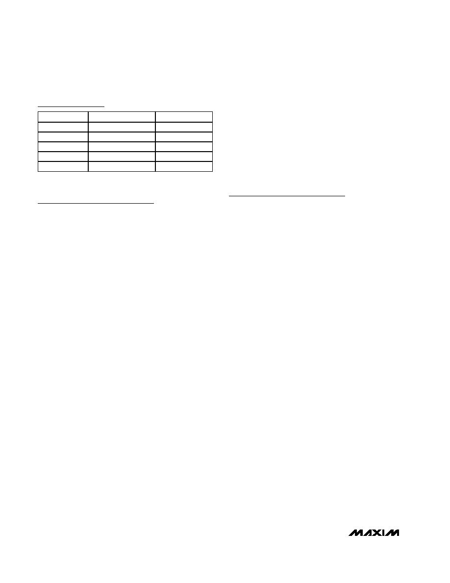
Ordering Information
PART
TEMP. RANGE
IC PACKAGE
MAX6951EVKIT
0∞C to +70∞C
16 QSOP
DESIGNATION
QTY
DESCRIPTION
D5, D6
2
200mA, 25V Schottky diodes
(SOT23)
Fairchild BAT54C
J1
1
DB25 male right-angle connector
J2
1
5-pin header
R1, R2, R3
3
10k
±5% resistors (0805)
R4
1
93.1k
±1% resistor (0805)
R5, R6
2
Not installed (0805)
U1
1
MAX6951EEE (16-pin QSOP)
U2
1
MAX604ESA (8-pin SO)
U3
1
MAX1841EUB (10-pin µMAX)
None
1
MAX6951 PC board
None
1
MAX6951 data sheet
None
1
MAX6951 EV kit data sheet
None
1
3 1/2in software diskette,
MAX6951 EV kit
Evaluates: MAX6951
Quick Start
Required Equipment
Before you begin, the following equipment is needed:
∑
IBM PC-compatible computer running Windows 95/98
∑
Computer monitor with 800 x 600 minimum screen
resolution
∑
Parallel printer port (25-pin female socket on the
back of the computer)
∑
Standard 25-pin, straight-through, male-to-female
cable (printer extension cable) to connect the com-
puter's parallel port to the MAX6951 EV kit
∑
DC power supply capable of supplying between
+4V to +6.5V and at least 500mA current
Procedure
Do not turn on the power until all connections are
made.
1) Connect a cable from the computer's parallel port to
the MAX6951 EV kit. Use a straight-through, 25-pin,
female-to-male cable. The EV kit software uses a
loopback connection to confirm that the correct port
has been selected.
2) The MAX6951.EXE software program can be run
from the floppy or hard drive. Use the Windows pro-
gram manager to run the program. If desired, you
may use the INSTALL.EXE program to copy the files
and create icons for them in the Windows 95/98 Start
menu. An uninstall program is included with the soft-
ware. Click on the UNINSTALL icon to remove the EV
kit software from the hard drive.
3) Connect the power-supply positive terminal to the
VIN pad and negative terminal to the GND pad.
4) Turn on the power supply and set it to +4V.
5) Start the MAX6951 program by opening its icon in
the Start menu.
6) Observe as the program automatically detects the
parallel port address of the MAX6951 EV kit and starts
the main program.
7) Header J2 is provided to monitor the parallel port pins
supplying the CLK_P, CS_P, DIN_P (+5V signals),
and loopback signals. The CLK, CS, and DIN pads
on the EV kit's left side are +3.3V level-shifted signals
from the MAX1841 level translator. Both signal loca-
tions can be used for monitoring.
Detailed Description
of Software
Note: Words in boldface are user-selectable features in
the software.
User Interface
The user interface is easy to operate. A mouse or the
Tab key can be used to navigate among various items of
the main display panel. Upon starting the program, the
MAX6951 EV kit display is programmed to initialize in
Normal mode, display 8-digits in No-decode mode,
blinking at a Slow Rate with an 8/16 (50% duty cycle)
display intensity, and display the contents of the initial-
ized MAX6951 SRAM Plane P0 and P1 contents. The
MAX6951 EV kit 8-digit LED display should alternate
between HELLO--Ø-- and --Ø--6951. Figure 1 is the main
panel for the MAX6951 EV kit.
Main Panel Display Controls
The Display mode group of radio buttons determines the
mode of operation of the MAX6951 EV kit. Clicking on the
Shutdown radio button puts the MAX6951 EV kit in shut-
down mode. The display is blank and the EV kit draws the
least amount of current in this mode. Selecting the
Normal radio button places the MAX6951 EV kit in the
normal mode of operation. Clicking on the Test radio but-
ton puts the MAX6951 EV kit in test mode. All eight digits
and all segment LEDs on the MAX6951 EV kit are illumi-
nated with a 50% duty cycle (8/16). To change the blink
rate, click on one of the Blink Rate radio buttons. Once
selected, the Blink Rate can be adjusted by using the
Up-Down Arrows on the keyboard. The 7-segment
digits on the computer monitor do not blink. Intensity of
the MAX6951 EV kit LEDs can be adjusted by using the
mouse to move the Intensity Control track bar. Once
selected, the Intensity Control can be adjusted with
the left-right arrows on the keyboard. The number of
digits displayed is adjusted with the Digit Scan Limit
button or list box. To set the scan limit to eight digits,
click on the Eight Digits button or use the mouse to
scroll the list box to the desired number of digits. Once
MAX6951 Evaluation Kit
2
_______________________________________________________________________________________
Component Suppliers
SUPPLIER
PHONE
FAX
Fairchild
888-522-5372
972-910-8036
Kemet
864-963-6300
864-963-6322
Murata
770-436-1300
770-436-3030
Sanyo
619-661-6835
619-661-1055
TDK
847-803-6100
847-390-4405
Note: When contacting suppliers, please indicate that you are
using the MAX6951.

the Digit Scan Limit list box is selected, the number
keys can be used to change values. If one digit is
desired, click on the One Digit button.
The SRAM Data Planes group of radio buttons select
which data plane is displayed on the computer monitor
7-segment digits and is updated when a digit value is
changed. Selecting the Plane P0 radio button displays
the contents of Plane P0 in the MAX6951. The program
keeps track of data written to all registers in the
MAX6951 hardware. Clicking on Plane P1 displays the
contents of Plane P1 written to hardware. Selecting
Plane P0 and P1 displays the contents of Plane P0 by
default. To clear the MAX6951 SRAM Plane registers
P0 and P1, click on the Clear Planes button.
Hexadecimal Decode Mode
The Digit Hexadecimal Decode checkboxes and but-
tons select which digits are represented in hexadecimal
decode mode. A
in a Digit checkbox indicates that the
digit is in hexadecimal decode mode. A blank Digit
checkbox indicates the digit is in No-decode mode.
Clicking on the All Digits button places all eight digits in
hexadecimal decode mode or clicking on None places
all digits in no-decode mode.
When a digit is in Hexadecimal Decode mode, the digit's
list box up-down arrows are used to select a value on
the numbered keypad once the digit's list box has been
selected. To activate a digit's decimal point, click on the
digit's decimal point with the mouse or click again to
deactivate the decimal point.
For digits in no-decode mode, use the mouse to click on
the desired segment of the digit's 7-segment display.
Note that the digit's list box up-down arrows are dis-
abled. To activate a digit's decimal point, click on the
digit's decimal point with the mouse or click again to
deactivate the decimal point. The left-side list box of each
Evaluates: MAX6951
MAX6951 Evaluation Kit
_______________________________________________________________________________________
3
Figure 1. Main Panel for MAX6951 EV Kit
Evaluates: MAX6951
digit displays the no-decode hex value written to the
MAX6951 hardware.
Digit 0 (left side) through digit 7 (right side) display the
contents of the selected MAX6951 SRAM data plane,
P0 or P1.
Pulldown Menus and Saving Data
All available functions except for changing a digit's
value can be changed using the pulldown menu. Hot
keys (Alt + underlined letter) provide an alternative to
using the mouse to configure the MAX6951 EV kit.
Pressing on the Save Data button saves all the current
registers and SRAM (P0 and P1) data to the program's
directory. Pressing on the Restore Data button
retrieves the saved register and SRAM (P0 and P1)
data and sends it to the MAX6951 EV kit hardware and
updates the main panel. Pressing the Clear Planes
button clears SRAM Planes P0 and P1.
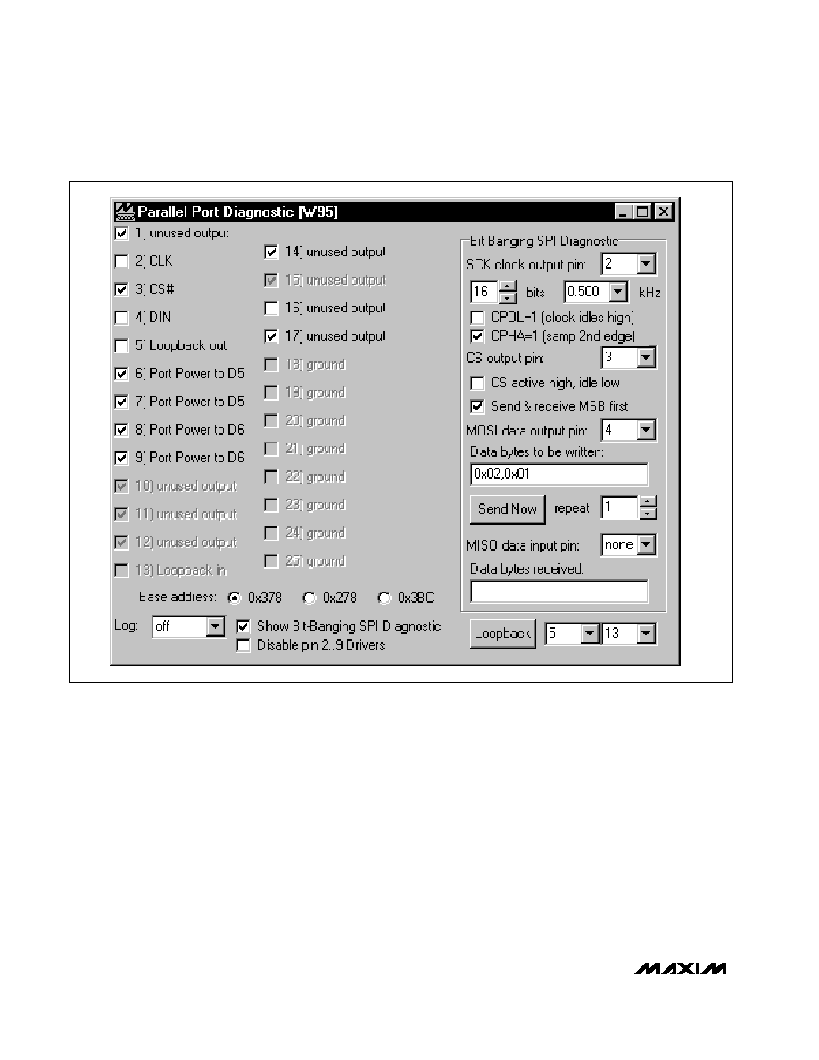
General-Purpose SPI Utility
There are two methods for communicating with the
MAX6951 (Figure 2): through the Main Panel display or
through the general-purpose SPI utility. The utility config-
ures the SPI parameters such as clock polarity (CPOL),
clock phase (CPHA), and chip select (CS) polarity. The
fields where pin numbers are required apply to the pins
of the parallel port connector. When using the SPI utility,
the Main Panel display no longer keeps track of changes
sent to hardware. The SPI utility is preconfigured for the
proper setting of CPOL, CPHA, and CS.
The utility only handles the data in byte (8-bit) format.
Data that is longer than a byte must be handled as mul-
MAX6951 Evaluation Kit
4
_______________________________________________________________________________________
Figure 2. SPI Utility Showing the Settings to Communicate with the MAX6951 EV Kit

tiple bytes. Thus, for the MAX6951 EV kit, 16-bit words
must be broken into two 8-bit bytes. Set the bits list box
to 16 so the clock sends 16 pulses on the CLK pin. The
command byte is entered first and then the data byte.
To write data to the MAX6951 EV kit hardware, enter
the data into the field: Data bytes to be written. The
data bytes must be hexadecimal and prefixed by 0x.
Separate each byte with a comma. Press the Send
Now button to write the data to the MAX6951 EV kit. For
example, to set the MAX6951 EV kit's display intensity
to 2/16, enter the command word 0x02 and data word
0x01, as: 0x02,0x01 and click the Send Now button.
Detailed Description
of Hardware
The MAX6951 EV kit demonstrates the MAX6951 8-digit
7-segment + dp common-cathode LED display driver
IC. The EV kit also features a MAX604 +3.3V LDO linear
regulator providing up to 500mA for the MAX6951 and
LEDs. The user can reconfigure JU6 to provide a volt-
age from +2.7V up to +5.5V to power the circuit. The
EV kit's input requires a +4VDC to +6.5VDC power sup-
ply capable of supplying at least 500mA for a +3.3V
evaluation. The EV kit's LDO linear regulator input volt-
age must be higher than the circuit voltage.
Additionally, an externally regulated +2.7V up to +5.5V
power supply can be used to power the EV kit,
EXT_VCC after reconfiguring jumper JU1.
The EV kit connects to an IBM-compatible PC computer
parallel port, which permits easy evaluation of the EV
kit. The EV kit's SPI-compatible serial interface is con-
nected to a MAX1841 (U3) level translator. The transla-
tor level-shifts the computer's parallel port logic +5V
signals to the EV kit's logic +3.3V or circuit voltage level
chosen by the user. By reconfiguring the appropriate
jumper (JU1), the translator can function with voltages
down to +2.7V. The level translator's parallel port side
is powered by parallel ports D5 to D7 data pins, diodes
D5/D6, and capacitor C7, which provide approximately
+5V to the translator DV
CC
input. The LDO linear regu-
lator supplies power to the translator's output side. A
five-pin header (J2) is provided for monitoring the +5V
CLK_P, CS_P, DIN_P nonlevel-translated, and LOOP-
BACK signals coming from the parallel port cable.
The EV kit can be easily reconfigured for stand-alone
operation and can be connected to an external micro-
controller for evaluation. Pullup resistors R1, R2, and R3
are provided on the EV kit for the MAX6951's CLK, CS,
and DIN pins. PC board pads are provided for interfac-
ing or monitoring the CLK, CS, and DIN +3.3V or circuit
voltage level chosen by the user, level-translated pins
of the MAX6951 IC.
The MAX6951 IC is configured to oscillate nominally at
4MHz by external capacitor C6 and resistor R4. The EV
kit can be reconfigured for evaluating other frequencies
by applying an external TTL/CMOS-compatible clock to
the EXT_OSC pad and reconfiguring jumper JU7. The
MAX6951's peak segment current is set to 20mA by
resistor R4.
The parallel port signals are level translated and
buffered from the EV kit by the MAX1841 level transla-
tor. However, the two sides are not galvanically isolat-
ed. Figure 3 shows the parallel port and level-transla-
tion interface for the MAX6951 EV kit.
Jumper Selection
MAX6951 EV Kit's Power Source
The MAX6951 EV kit can be easily powered by a sepa-
rate externally regulated power supply. The 2-pin
jumper JU1 selects the power source for the EV kit cir-
cuit. The external power source must be in the +2.7V to
+5.5V range and must be capable of supplying at least
500mA current. The output of the EV kit's built-in LDO
power regulator must be isolated from the external
power supply. Table 1 lists the jumper options.
Stand-Alone Configuration
The MAX6951 EV kit features several jumpers to recon-
figure the EV kit for stand-alone operation or PC/soft-
ware control. The 2-pin jumpers, JU2 to JU5, select the
evaluation mode for the EV kit. Table 2 lists the jumpers
to cut open or short for the desired evaluation mode.
Note: All jumpers must be configured for only one
mode at a time and the proper voltage selected for
stand-alone mode.To select other output voltages
Evaluates: MAX6951
MAX6951 Evaluation Kit
_______________________________________________________________________________________
5
EIGHT 7-SEGMENT DIGITS
MAX604
LDO
MAX6951
MAX1841
5V
3.3V
5V
+3.3V SIDE
+5V SIDE
MAX6951
EV KIT
+4V TO +6.5V
POWER SUPPLY
OPTIONAL USER EXTERNAL
REGULATED PS
(+2.7V TO +5.5V)
PC PARALLEL
PORT CABLE
5V PC
SIGNALS
(*)
* +3.3V OR USER-SETTABLE VOLTAGE
Figure 3. MAX6951 EV Kit Level-Translation Functional
Diagram