 | –≠–ª–µ–∫—Ç—Ä–æ–Ω–Ω—ã–π –∫–æ–º–ø–æ–Ω–µ–Ω—Ç: MAX7450 | –°–∫–∞—á–∞—Ç—å:  PDF PDF  ZIP ZIP |

General Description
The MAX7450/MAX7451/MAX7452 complete front-end
video-signal conditioners are designed to improve the
quality of standard-definition video signals. The devices
restore the DC level of the video input, correct for
amplitude errors up to ±6dB, detect fault conditions,
and filter out-of-band noise. The MAX7450/MAX7451/
MAX7452 optimize the signal quality for further video
processing through a crosspoint switch or video
decoder (ADC). Each device integrates an input video
clamp, automatic gain control (AGC), loss-of-sync
(LOS) detector, and an out-of-band noise/lowpass filter.
These devices also incorporate a user-selectable
buffer gain (0 or +6dB) and an AGC-disable function.
The MAX7450 and MAX7451 operate from dual power
supplies of ±5V or ±3.3V respectively, and they restore
the video blanking level to GND. The MAX7452 operates
from a single +5V supply and features a user-adjustable
clamp level.
The devices are available in an 8-pin SO package with
an exposed pad and are specified for operation over
the extended (-40
∞C to +85∞C) temperature range.
Applications
Signal Conditioner for Standard-Definition
Video Inputs
Security Video Systems
Video-Switching Systems
Features
Back-Porch Clamp to GND (MAX7450/MAX7451)
Adjustable Back-Porch Clamp (MAX7452)
Automatic Gain Control (±6dB Range) Normalizes
Signals to Standard Video Level
Input Fault Detection with LOS Output
Inherent 50Hz/60Hz Input Rejection of 60dB
Single-Supply Operation: MAX7452 (+5V)
Out-of-Band Noise Filter
Output Buffer Drives Standard 150 Video Load
with 0dB or +6dB Gain
Dual-Supply Operation
MAX7450 (±5V)
MAX7451 (±3.3V)
Tiny 8-Pin SO Package
MAX7450/MAX7451/MAX7452
Video-Signal Conditioners with AGC and
Back-Porch Clamp
________________________________________________________________ Maxim Integrated Products
1
Ordering Information
19-3267; Rev 2; 11/04
For pricing, delivery, and ordering information, please contact Maxim/Dallas Direct! at
1-888-629-4642, or visit Maxim's website at www.maxim-ic.com.
PART
TEMP RANGE
PIN-
PACKAGE
SUPPLY
VOLTAGE (V)
MAX7450ESA
-40
∞C to +85∞C 8 SO-EP*
±
5
MAX7451ESA
-40
∞C to +85∞C 8 SO-EP*
±
3.3
MAX7452ESA
-40
∞C to +85∞C 8 SO-EP*
+5
MAX7450
MAX7451
NOISE
FILTER
V
CC
V
SS
75
75
LOS
SYNC SEPARATOR
AND AMPLITUDE
DETECTOR
AGCD
IN
OUT
VIDEO
INPUT
GND
±6dB
0 OR +6dB
GAIN SET (0dB OR +6dB)
Functional Diagram
*EP = Exposed pad.
Package code = S8E-12.

MAX7450/MAX7451/MAX7452
Video-Signal Conditioners with AGC and
Back-Porch Clamp
2
_______________________________________________________________________________________
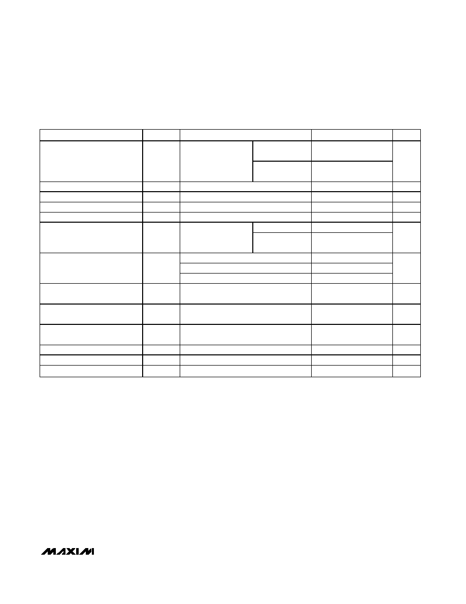
ABSOLUTE MAXIMUM RATINGS
ELECTRICAL CHARACTERISTICS
(V
SUPPLY
= ±5V ±5% (MAX7450), V
SUPPLY
= ±3.3V ±5% (MAX7451), V
SUPPLY
= +5V ±5% (MAX7452), R
L
=150
to GND, C
L
= 0 to
20pF, GSET = 1, AGCD = 1, T
A
= T
MIN
to T
MAX
, unless otherwise noted. Typical values are at T
A
= +25
∞C.)
Stresses beyond those listed under "Absolute Maximum Ratings" may cause permanent damage to the device. These are stress ratings only, and functional
operation of the device at these or any other conditions beyond those indicated in the operational sections of the specifications is not implied. Exposure to
absolute maximum rating conditions for extended periods may affect device reliability.
V
CC
to GND
MAX7450/MAX7452...........................................................+6V
MAX7451 ...........................................................................+4V
V
SS
to GND
MAX7450.............................................................................-6V
MAX7451.............................................................................-4V
OUT
MAX7450/MAX7451 ..........................................-2.5V to +3.5V
MAX7452 ................................................-0.3V to (V
CC
+ 0.3V)
GSET, AGCD, LOS .....................................-0.3V to (V
CC
+ 0.3V)
All Other Pins
MAX7450/MAX7451...................(-0.3V + V
SS
) to (V
CC
+ 0.3V)
MAX7452 ................................................-0.3V to (V
CC
+ 0.3V)
Maximum Current into Any Pin ....................................±50mA
Continuous Power Dissipation (T
A
= +70∞C)
8-Pin SO (derate 18.9mW/∞C above +70∞C)..............1509mW
Operating Temperature Range ...........................-40∞C to +85∞C
Storage Temperature Range .............................-65∞C to +150∞C
Junction Temperature ......................................................+150∞C
Lead temperature (soldering, 10s) ..................................+300∞C
PARAMETER
SYMBOL
CONDITIONS
MIN
TYP
MAX
UNITS
MAX7450/MAX7451, relative to GND
±50
Clamp Accuracy
MAX7452, relative V
BPLVL
= 1.5V
±50
mV
GSET = 0
1.5
2.4
Back-Porch Level Input Range
V
BPLVL
MAX7452
GSET = 1
1.2
2.0
V
Clamp Response Time
t
CLAMP
Blanking level at the output to 1% of final
value
70
Lines
GSET = 0, relative
to V
OUT
= 1V
P-P
±10
AGC Accuracy
AGCD = 0,
V
IN
= 0.5V
P-P
to 2V
P-P
GSET = 1, relative
to V
OUT
= 2V
P-P
±10
%
AGC Input Range
AGCD = 0, relative to V
IN
= 1V
P-P
-6.0
+6.0
dB
Gain Flatness
G
F
f = 5MHz relative to 100kHz
-0.3
+0.3
dB
Noise-Filter Cutoff
Fc
10
MHz
GSET = 0
0.95
1
1.05
Low-Frequency Gain
f = 100kHz
GSET = 1
1.85
2
2.05
V/V
Group-Delay Deviation
t
G
3.58/4.43MHz relative to 100kHz
15
ns
Differential Gain
dG
Five-step modulated staircase (V
IN
= 1V
P-P
)
0.2
0.6
%
Differential Phase
d
Five-step modulated staircase (V
IN
= 1V
P-P
)
0.2
0.6
Degrees
MAX7450/MAX7451/MAX7452
Video-Signal Conditioners with AGC and
Back-Porch Clamp
_______________________________________________________________________________________
3
ELECTRICAL CHARACTERISTICS (continued)
(V
SUPPLY
= ±5V ±5% (MAX7450), V
SUPPLY
= ±3.3V ±5% (MAX7451), V
SUPPLY
= +5V ±5% (MAX7452), R
L
=150
to GND, C
L
= 0 to
20pF, GSET = 1, AGCD = 1, T
A
= T
MIN
to T
MAX
, unless otherwise noted. Typical values are at T
A
= +25
∞C.)
PARAMETER
SYMBOL
CONDITIONS
MIN
TYP
MAX
UNITS
GSET = 0,
V
OUT
= 1V
P-P
68
Signal-to-Noise Ratio
SNR
Output signal
peak-to-peak to RMS
noise (100Hz to 5MHz)
GSET = 1,
V
OUT
= 2V
P-P
65
dB
Line Time Distortion
H
DIST
18µs, 100 IRE bar
0.2
%
Field Time Distortion
V
DIST
130 lines, 18µs, 100IRE bar
0.5
%
Input Leakage Current
I
IN
1
5
µA
Output Dynamic Range
V
IN
= 1V
P-P
, dG / dP < 3% / degrees
2
2.4
V
P-P
AGCD = 1
30
Power-Supply Rejection Ratio
PSRR
V
CC
+ 100mV
P-P
,
f = 3.5MHz
AGCD = 0 with
maximum gain
20
dB
MAX7450
35
MAX7451
30
Supply Current
MAX7452
20
mA
Logic-High Input
V
IH
0.7 x
V
CC
V
Logic-Low Input
V
IL
0.3 x
V
CC
V
Logic-High Output
V
OH
I
SOURCE
= 500µA
V
CC
-
0.5
V
Logic-Low Output
V
OL
I
SINK
= 500µA
0.4
V
Input Current Logic-High
I
IH
Logic input sink
10
µA
Input Current Logic-Low
I
IL
Logic input source
10
µA

MAX7450/MAX7451/MAX7452
Video-Signal Conditioners with AGC and
Back-Porch Clamp
4
_______________________________________________________________________________________
Typical Operating Characteristics
V
SUPPLY
= ±5V ±5% (MAX7450), V
SUPPLY
= ±3.3V ±5% (MAX7451), V
SUPPLY
= +5V ±5% (MAX7452), R
L
= 150
to GND, C
L
= 0 to
20pF, GSET = 1, AGCD = 1. T
A
= +25
∞C, unless otherwise noted.
GROUP DELAY vs. FREQUENCY
MAX7450 toc01
FREQUENCY (MHz)
GROUP DELAY (ns)
1
20
30
40
50
60
10
0.1
10
2T RESPONSE
MAX7450 toc02
t = 200ns/div
IN
200mV/div
OUT
200mV/div
DIFFERENTIAL GAIN
MAX7450 toc03
DIFFERENTIAL PHASE (DEGREES)
1st
3rd
2nd
4th
5th
6th
DIFFERENTIAL GAIN (%)
0.2
0.4
0
-0.2
-0.4
0.2
0.1
0.3
0
-0.2
-0.1
-0.3
DIFFERENTIAL PHASE
1st
3rd
2nd
4th
5th
6th
PASSBAND AMPLITUDE vs. FREQUENCY
MAX7450 toc04
FREQUENCY (MHz)
AMPLITUDE (dB)
1
-8
-6
-4
-2
0
2
4
6
8
-10
0.1
10
GAIN = 2V / V
GAIN = 1V / V
AMPLITUDE vs. FREQUENCY
MAX7450 toc05
FREQUENCY (MHz)
AMPLITUDE (dB)
1
10
-70
-60
-50
-40
-30
-20
-10
0
10
0.1
100
GAIN = 1V / V
GAIN = 2V / V
SUPPLY CURRENT vs. TEMPERATURE
MAX7450 toc06
TEMPERATURE (
∞C)
SUPPLY CURRENT (mA)
60
35
10
-15
27
29
31
33
35
25
-40
85
MAX7450
BACK-PORCH VOLTAGE
vs. TEMPERATURE
MAX7450 toc07
TEMPERATURE (
∞C)
BACK-PORCH VOLTAGE (mV)
60
35
10
-15
-5
-4
-3
-2
-1
0
-6
-40
85
MAX7450
MAX7450/MAX7451/MAX7452
Video-Signal Conditioners with AGC and
Back-Porch Clamp
_______________________________________________________________________________________
5
PIN
MAX7450/
MAX7451
MAX7452
NAME
FUNCTION
1
1
V
CC
Positive Power Supply. Connect +5V to V
CC
for the MAX7450/MAX7452. Connect +3.3V to V
CC
for the MAX7451. Bypass to GND with 1µF and 0.1µF capacitors as close to the pin as possible.
2
2
IN
Video Input. AC-couple video signal through a 0.1µF capacitor.
3
3
GND
Ground
4
--
V
SS
Negative Power Supply. Connect -5V to V
SS
for the MAX7450. Connect -3.3V to V
SS
for the
MAX7451. Bypass to GND with 1µF and 0.1µF capacitors as close to the pin as possible.
--
4
BPLVL
Back-Porch Level Input. When gain = 2V/V (GSET = 1), output back-porch level is equal to
BPLVL input. When gain = 1V/V (GSET = 0), output back-porch level is equal to V
BPLVL
/1.5.
5
5
AGCD
Automatic Gain-Control Disable Input. Disable AGC by driving AGCD to V
CC
. Enable AGC by
driving AGCD to GND.
6
6
OUT
Video Output
7
7
GSET
Gain-Setting Input. Drive GSET high to set buffer gain to +6dB. Drive GSET low to set buffer
gain to 0dB.
8
8
LOS
Loss-of-Sync Logic Output. LOS is high when video sync is lost for more than 15 horizontal
lines. LOS goes low when video sync is present.
--
--
EP
Exposed Pad. Connect to V
SS
(MAX7450/MAX7451). Connect to GND (MAX7452).
Pin Description
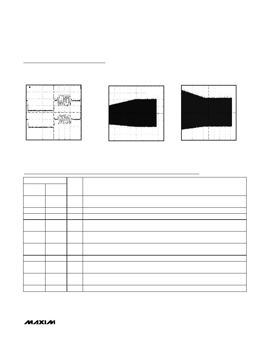
OUTPUT BACK-PORCH LEVEL (MAX7450)
MAX7450 toc08
1
µs
IN
AC-COUPLED
200mV/div
OUT
200mV/div
BACK-PORCH = 0V
AGC RESPONSE ENVELOPE (V
IN
= 0.5V
P-P
)
MAX7450 toc09
400ms/div
500mV/div
AGCD = 0
V
OUT
= 2V
P-P
AGC RESPONSE ENVELOPE (V
IN
= 2V
P-P
)
MAX7450 toc10
400ms/div
500mV/div
AGCD = 0
V
OUT
= 2V
P-P
Typical Operating Characteristics (continued)
V
SUPPLY
= ±5V ±5% (MAX7450), V
SUPPLY
= ±3.3V ±5% (MAX7451), V
SUPPLY
= +5V ±5% (MAX7452), R
L
= 150
to GND, C
L
= 0 to
20pF, GSET = 1, AGCD = 1. T
A
= +25
∞C, unless otherwise noted.