 | –≠–ª–µ–∫—Ç—Ä–æ–Ω–Ω—ã–π –∫–æ–º–ø–æ–Ω–µ–Ω—Ç: MAX769 | –°–∫–∞—á–∞—Ç—å:  PDF PDF  ZIP ZIP |

________________General Description
The MAX769 is a complete buck/boost power supply
and monitoring system for two-way pagers or other low-
power digital communications devices. Few external
components are required. Included on-chip are:
∑
An 80mA output, synchronous-rectified, buck/boost
DC-DC converter with a digitally controlled +1.8V to
+4.9V output. The DC-DC converter is unique, since
it provides a regulated output for battery inputs that
are both less than and greater than the output volt-
age, without using transformers.
∑
Three low-noise linear-regulator outputs
∑
Three DAC-controlled comparators for software-
driven, 3-channel A/D conversion
∑
SPITM-compatible serial interface
∑
Reset and low-battery (LBO) warning outputs
∑
Charger for NiCd/NiMH, lithium battery, or storage
capacitor for RF PA power or system backup
∑
Two 1.8
(typical), serial-controlled, open-drain
MOSFET switches for beeper or vibrator drive
An evaluation kit for the MAX769 (MAX769EVKIT) is
available to aid in design and prototyping.
____________________________Features
o
Regulated Step-Up/Step-Down Operation
o
80mA Output from 3 Cells
o
85% Efficiency
o
13µA Idle ModeTM (coast) Current
o
Selectable Low-Noise PWM or Low-Current PFM
Operation
o
PWM Operating Frequency Synchronized to
Seven Times an External Clock Source
o
Operates at 270kHz with No External Clock
o
Automatic Backup-Battery Switchover
________________________Applications
Two-Way Pagers
GPS Receivers
2 or 3-Cell Powered, Hand-Held Equipment
MAX769
2 or 3-Cell, Step-Up/Down,
Two-Way Pager System IC
________________________________________________________________
Maxim Integrated Products
1
MAX769
INPUT
2 OR 3 AA ALKALINE BATTERIES
1.5V TO 5.5V
BATT
LX2
OUT
PGND
REG2IN
OFS
REG2
OUTPUT 2
2.85V ANALOG
LOW-BATTERY
IN/OUT
REJECT
IN/OUT
SERIAL
I/O
1.8
DRIVERS
A/D
INPUT
OPTIONAL
OUTPUT 1
3V LOGIC
OUTPUT 3
1V RECEIVER
TO RF PA
NiCd
BATTERY OR
STACK
REG1
REG3
NICD
AGND
REF
FILT
LBI
LBO
RSIN
RSO
CS
SCL
SD1
SD03
DR1
DR2
DR2IN
DRGND
CH0
SYNC
LX1
STORAGE
CAPACITOR
___________________________________________________Typical Operating Circuit
19-4771; Rev 1; 10/98
PART
MAX769EEI
-40∞C to +85∞C
TEMP. RANGE
PIN-PACKAGE
28 QSOP
Ordering Information
Idle Mode is a trademark of Maxim Integrated Products. SPI is a trademark of Motorola, Inc.
Pin Configuration appears at end of data sheet.
For free samples & the latest literature: http://www.maxim-ic.com, or phone 1-800-998-8800.
For small orders, phone 1-800-835-8769.
EVALUATION KIT MANUAL
FOLLOWS DATA SHEET

MAX769
2 or 3-Cell, Step-Up/Down,
Two-Way Pager System IC
2
_______________________________________________________________________________________
ABSOLUTE MAXIMUM RATINGS
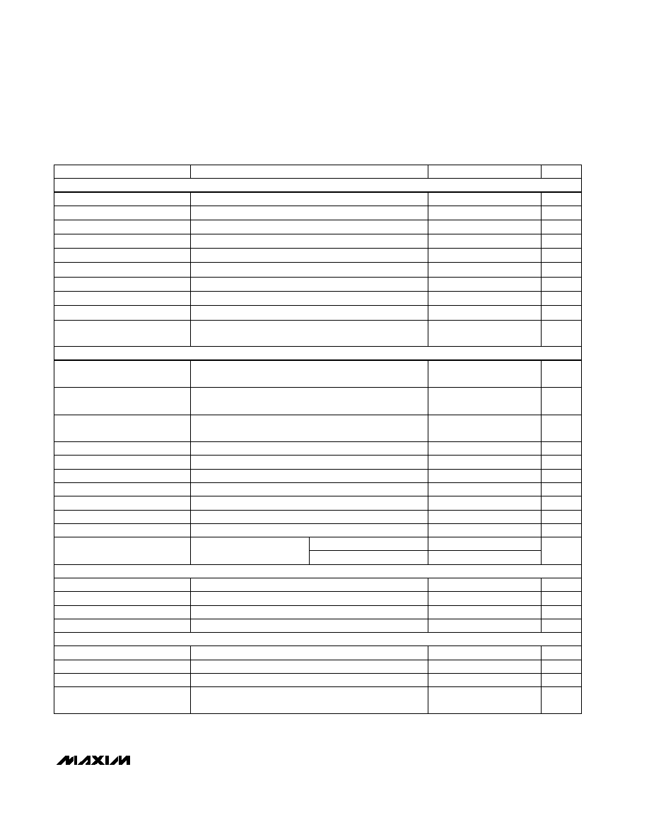
ELECTRICAL CHARACTERISTICS
(OUT = 3.0V, BATT = 3.6V, T
A
= -40∞C to +85∞C, unless otherwise noted. Typical values are at T
A
= +25∞C.) (Note 1)
Stresses beyond those listed under "Absolute Maximum Ratings" may cause permanent damage to the device. These are stress ratings only, and functional
operation of the device at these or any other conditions beyond those indicated in the operational sections of the specifications is not implied. Exposure to
absolute maximum rating conditions for extended periods may affect device reliability.
BATT, OUT, NICD, LBO, RSO to AGND...................-0.3V to +6V
REG1, REG2, OFS, REF, R2IN to AGND .....-0.3V to (OUT + 0.3V)
SCL, SDO, SDI, CS, SYNC, FILT, DR2IN,
CH0, LBI, RSIN to AGND......................-0.3V to (REG1 + 0.3V)
REG3 .......................................................-0.3V to (REG2 + 0.3V)
DR1, DR2 to DRGND ...............................-0.3V to (BATT + 0.3V)
PGND, DRGND to AGND ......................................-0.3V to +0.3V
LX1 to PGND .............................................-0.3V to (OUT + 0.3V)
LX2 to PGND ............................................-0.3V to (BATT + 0.3V)
Continuous Power Dissipation (T
A
= +70∞C)
QSOP (derate 8mW/∞C above +70∞C) ..........................640mW
Operating Temperature Range ...........................-40∞C to +85∞C
Junction Temperature ......................................................+150∞C
Storage Temperature Range .............................-65∞C to +165∞C
Lead Temperature (soldering, 10sec) .............................+300∞C
I
REF
= 0 to 20µA, OUT = 1.8V to 4.9V
V
-1.5%
1.28
1.5%
T
A
= +25∞C
Reference Voltage
I
DR
= 120mA
Run or Coast Mode
1.8
2.8
DR1, DR2 On-Resistance
V
DR
= 5V
nA
1
250
DR1, DR2 Leakage Current
Charger and Backup Modes off, NICD = 3.6V
µA
Incremental supply current when on
REG2, REG3 and CH DAC off, V
OUT
= 2.8V
REG2, REG3 and CH DAC on
Coast Mode
1.2
3
Incremental supply current when on
T
A
= +25∞C
CONDITIONS
T
A
= -40∞C to +85∞C
I
SDO
= 100µA
mV
200
SDO Output Low
I
SDO
= -100µA, from REG1
V
V
REG1
- 0.2
SDO Output High
Includes CS, SDI, SCL, DR2IN, and SYNC
V
0.4
Logic Input Level Low
Includes CS, SDI, SCL, DR2IN, and SYNC
V
V
REG1
- 0.4
Logic Input Level High
3.6
Charger and Backup Modes off, BATT = 0V,
OUT = 0V
µA
1.2
3
NICD Input Current, Power Fail
(Note 8)
Logic Input = 0 to 3.3V; includes CS, SDI, SCL,
DR2IN, and SYNC
µA
V
1.6
2.0
-1
1
BATT Minimum Start-Up Voltage
(Note 3)
V
1.5
5.5
Logic Input Current
NICD Input Current, Standby
(Note 6)
BATT Typical Operating Range
(Note 2)
Incremental supply current when on
µA
Backup Mode, NICD = 3.6V, OUT = 3V
50
REG2 Supply Current (Note 4)
µA
20
40
NICD Input Supply Current, Backup
(Note 7)
µA
30
CH DAC Supply Current (Note 4)
µA
13
25
Coast Mode Supply Current (Note 4)
µA
875
1350
Run Mode Supply Current (Note 4)
µA
4
10
BATT Supply Current (Note 5)
µA
20
REG3 Supply Current (Note 4)
UNITS
MIN
TYP
MAX
PARAMETER
GENERAL PERFORMANCE
MAX769
2 or 3-Cell, Step-Up/Down,
Two-Way Pager System IC
_______________________________________________________________________________________
3
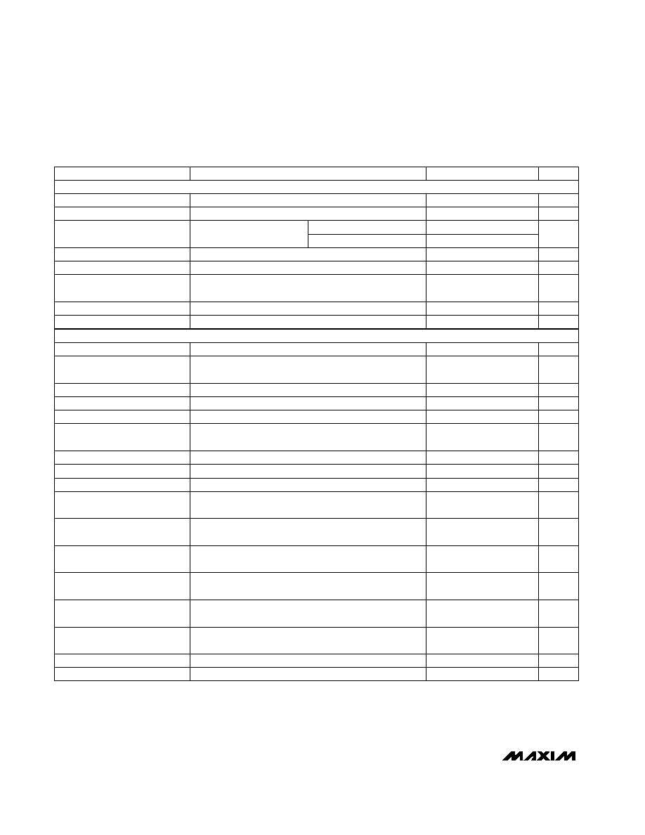
ELECTRICAL CHARACTERISTICS (continued)
(OUT = 3.0V, BATT = 3.6V, T
A
= -40∞C to +85∞C, unless otherwise noted. Typical values are at T
A
= +25∞C.) (Note 1)
%
-3.5
3.5
OUT Error, Coast Mode
(Note 11)
%
Coast Mode, OUT = 1.8V to 4.9V
-3.5
3.5
OUT Error, Run Mode (Note 12)
Circuit of Figure 2, OUT = 3.0V, BATT = 3.0V
Run Mode, OUT = 1.8V to 4.9V
Circuit of Figure 2, OUT = 3.0V, BATT = 3.0V
CONDITIONS
BATT = 1.6V to 4.5V
mV
25
OUT Line Regulation
I
OUT
= 80mA, C
OUT
= 47µF with ESR < 0.25
mVp-p
70
OUT Voltage Ripple
LX1, LX2, BATT = 3.0V
0.9
1.8
LX On-Resistance (Note 14)
ns
50
ns
50
CS to SCL Hold Time (t
CSH
)
CS to SCL Setup Time (t
CSS
)
ns
100
SDI Setup Time (t
DS
)
NMOS
PMOS
1.3
2.6
T
A
= +25∞C, FILT connected to REF
kHz
210
270
325
Frequency, Free-Run
Backup Mode, NICD = 3.3V
f
SYNC
= 38.4kHz
ns
100
kHz
CS Pulse Width High (t
CSW
)
268.8
ns
70
Frequency, Locked
CS to SDO Disable (t
TR
)
f
SYNC
= 38.4kHz, FILT Network = 1nF
(22nF + 10k
)
kHz
±15
Jitter (Note 15)
5
10
f
SYNC
= 38.4kHz, FILT Network = 1nF
(22nF + 10k
)
ms
1
25
Capture Time (Note 15)
Backup-Regulator
On-Resistance (Note 16)
ns
50
0.2V < (OUT - NICD) < 2V, 15mA_CHG = 1
SCL Pulse Width High or Low
(t
CH
, t
CL
)
mA
mA
80
115
7
25
Output Current, Run Mode
(Note 10)
mA
15
40
Current High
Output Current, Coast Mode
(Note 10)
UNITS
MIN
TYP
MAX
PARAMETER
0.2V < (OUT - NICD) < 2V, 1mA_CHG = 1
mA
0.45
1.5
Current Low
OUT = 2.8V, I
OUT
= 20mA, NICD = 3.3V
%
-3.5
3.5
OUT Error, Backup Regulator
50% duty cycle
MHz
5
SCL Maximum Clock Rate
OUT = 3.0V
%
76
83
Maximum LX Duty Cycle
During the inductor charge cycle
mA
300
350
400
LX Switch Current Limit
ns
70
ns
70
CS to SDO Output Valid (t
DV
)
SCL to SDO Output Valid (t
DO
)
ns
50
SDI Hold Time (t
DH
)
I
OUT
= 1mA to 80mA, Run Mode
mV
25
OUT Load Regulation
Coast or Run Mode, OUT = 1.8V to 4.9V
mV
30
100
170
OUT DAC Step Size (Note 13)
SERIAL-INTERFACE TIMING SPECIFICATIONS
(Note 9)
DC-DC CONVERTER
PHASE-LOCKED LOOP (PLL)
NICD CHARGER
V
MAX769
2 or 3-Cell, Step-Up/Down,
Two-Way Pager System IC
4
_______________________________________________________________________________________
ELECTRICAL CHARACTERISTICS (continued)
(OUT = 3.0V, BATT = 3.6V, T
A
= -40∞C to +85∞C, unless otherwise noted. Typical values are at T
A
= +25∞C.) (Note 1)
10mV overdrive
REG3 Output Voltage
µs
I
REG3
= 0 to 2mA
0.96
1.0
1.04
V
I
REG2
= 0 to 24mA, OUT = 3.0V, R
OFS
= 15k
mV
120
155
190
REG2 Voltage Drop
3.2
3.3
3.4
15
50
LBO/RSO Response Time
(Note 16)
OUT = 3.0V, I
REG1
= 65mA
f = 268.8kHz, C
REG1
= 10µF ceramic
Falling input
CONDITIONS
V
f = 268.8kHz, C
REG1
= 10µF, ceramic, R
OFS
= 15k
,
C
OFS
= 0.1µF, I
REG2
= 15mA
dB
30
40
REG2 Supply Rejection
(Note 16)
f = 268.8kHz, C
REG1
= 1µF ceramic
dB
40
50
REG3 Supply Rejection (Note 16)
0.58
0.60
0.63
LBI/RSIN Input Threshold
At thresholds of 200mV, 800mV, and 1270mV
%
-2.0
2.0
- 15mV
+ 15mV
CH0 Error
At thresholds of 1200mV, 3200mV, and 5080mV
%
-3.0
3.0
- 60mV
+ 60mV
mV
10
CH0 Threshold Resolution
(Note 16)
V
0.2
1.27
CH0 Threshold Range (Note 16)
Measures NICD
V
1.2
5.08
CH1 Threshold Range (Note 16)
Measures BATT
V
CH1 Error
I
REG2
= 0.1mA to 24mA
mV
nA
-50
-3
50
LBI/RSIN Input Current
1.2
5.08
I
OUT
= 1mA
CH2 Threshold Range (Note 16)
Measures BATT
mV
mV
40
CH2 Threshold Resolution
(Note 16)
30
400
LBO/RSO Output Low
Measures NICD
mV
Output = 5.5V
nA
1
250
LBO/RSO Output Leakage
40
CH1 Threshold Resolution
(Note 16)
1.5
3.1
REG1 PMOS On-Resistance
dB
15
25
mV
REG1 Supply Rejection (Note 16)
7.5
16
30
LBI/RSIN Input Hysteresis
(Note 16)
9
REG2 Load Regulation
UNITS
MIN
TYP
MAX
PARAMETER
I
OUT
= 1mA, OUT = 4.9V
V
3.15
3.45
REG1 Clamp Voltage
T
A
= +25∞C
T
A
= -40∞C to +85∞C
At thresholds of 1200mV, 3200mV, and 5080mV
%
-3.0
3.0
- 60mV
+ 60mV
CH2 Error
mV
1
2
4
CH0 Input Hysteresis (Note 16)
LINEAR REGULATORS
DATA-ACQUISITION AND VOLTAGE MONITORS
CH1 Input Hysteresis (Note 16)
4
8
16
mV

MAX769
2 or 3-Cell, Step-Up/Down,
Two-Way Pager System IC
_______________________________________________________________________________________
5
ELECTRICAL CHARACTERISTICS (continued)
(OUT = 3.0V, BATT = 3.6V, T
A
= -40∞C to +85∞C, unless otherwise noted. Typical values are at T
A
= +25∞C.) (Note 1)
Note 1:
Specifications to -40∞C are guaranteed by design, not production tested.
Note 2:
This is not a tested parameter, since the IC is powered from OUT, not BATT.
Note 3:
Minimum start-up voltage is tested by determining when the LX pins can draw at least 15mA for 0.5µs (min) at a 285kHz
(min) repetition rate. This guarantees that the IC will deliver at least 200µA at the OUT pin.
Note 4:
This supply current is drawn from the OUT pin. Current drain from the battery depends on voltages at BATT and OUT and
on the DC-to-DC converter's efficiency.
Note 5:
Current into BATT pin in addition to the supply current at OUT. This current is roughly constant from Coast to Run Mode.
Note 6:
Current into NICD pin when NICD isn't being charged and isn't regulating OUT.
Note 7:
Current into NICD pin when NICD is regulating OUT. Doesn't include current drawn from OUT by the rest of the circuit.
Measured by setting the OUT regulation point to 2.8V and holding OUT at 3.0V.
Note 8:
Current into the NICD pin when BATT and OUT are both at 0V. This test guarantees that NICD won't draw significant cur-
rent when the main battery is removed and backup is not activated.
Note 9:
Serial-interface timing specifications are not tested and are provided for design guidance only. Serial-interface functionali-
ty is tested by clocking data in at 5MHz with a 50% duty-cycle clock and checking for proper operation. With OUT set
below 2.5V, the serial-interface clock frequency should be reduced to 1MHz to ensure proper operation.
Note 10:
This specification is not directly tested but is guaranteed by correlation to LX on-resistance and current-limit tests.
Note 11:
Measured by using the internal feedback network and Coast-Mode error comparator to regulate OUT. Doesn't include
ripple voltage due to inductor currents.
Note 12:
Measured by using the internal feedback network and Run-Mode error comparator to regulate OUT. Doesn't include ripple
voltage due to inductor currents.
Note 13:
Uses the OUT measurement techniques described for the OUT error, Coast Mode, and OUT error Run Mode specifica-
tions.
Note 14:
The on-resistance is for either LX1 or LX2.
Note 15:
PLL acquisition characteristics depend on the impedance at the FILT pin. The specification is not tested and is provided
for design guidance only.
Note 16:
The limits in this specification are not guaranteed and are provided for design guidance only.
CH0 = 0.2V to 1.27V
nA
-100
100
CH0 Input Current
10mV overdrive
µs
0.6
1.0
CH Comparator Response Time
(Note 16)
CONDITIONS
mV
4
8
16
CH2 Input Hysteresis (Note 16)
UNITS
MIN
TYP
MAX
PARAMETER
Typical Operating Characteristics
(T
A
= +25∞C, unless otherwise noted.)
100
50
1
10
100
EFFICIENCY vs. LOAD CURRENT
(RUN MODE, V
OUT
= 3.0V)
60
MAX769-01
LOAD CURRENT (mA)
EFFICIENCY (%)
70
80
90
V
IN
= 5.0V
V
IN
= 1.5V V
IN
= 2.0V
V
IN
= 3.5V
V
IN
= 2.5V
100
50
0.01
1
10
0.1
100
EFFICIENCY vs. LOAD CURRENT
(COAST MODE, V
OUT
= 3.0V)
60
MAX769-02
LOAD CURRENT (mA)
EFFICIENCY (%)
70
80
90
V
IN
= 5.0V
V
IN
= 3.5V
V
IN
= 2.5V
V
IN
= 2.0V
V
IN
= 1.5V
100
50
0.01
1
10
0.1
100
EFFICIENCY vs. LOAD CURRENT
(COAST MODE, V
OUT
= 2.4V)
60
MAX769-03
LOAD CURRENT (mA)
EFFICIENCY (%)
70
80
90
V
IN
= 5.0V
V
IN
= 3.5V
V
IN
= 2.5V
V
IN
= 2.0V
V
IN
= 1.5V