 | –≠–ª–µ–∫—Ç—Ä–æ–Ω–Ω—ã–π –∫–æ–º–ø–æ–Ω–µ–Ω—Ç: MAX8601 | –°–∫–∞—á–∞—Ç—å:  PDF PDF  ZIP ZIP |

General Description
The MAX8600/MAX8601 single-/dual-input linear bat-
tery chargers safely charge single-cell Li+ batteries.
The charging rate is optimized to accommodate the
thermal characteristics of a given application. There is
no need to reduce the maximum charge current or
worst-case charger power dissipation. Charging is opti-
mized for Li+ cells using a control algorithm that
includes low-battery precharging, voltage and current-
limited fast-charging, and top-off charging, while con-
tinuously monitoring the battery for overvoltage,
over/undertemperature, and charging time. The charg-
er timeout protection is programmable. The charger
status is indicated by three open-drain outputs.
The MAX8601 automatically selects between either a
USB or AC adapter input source. The AC adapter
charge current is programmable, while USB charge
current is set not to exceed either 100mA or 500mA,
depending on the USEL input. The MAX8600 is a sin-
gle-input charger with no USB source input.
The MAX8600/MAX8601 are available in the tiny 3mm x
3mm power-enhanced TDFN package.
Applications
Cell Phones
Portable Media Players
Digital Cameras
MP3 Players
PDAs
Wireless Appliances
Features
Single- (MAX8600) or Dual- (MAX8601) Input Li+
Charger
Up to 1A Programmable Fast-Charge
100mA/500mA USB Select Input (MAX8601)
±5% Fast-Charge Current-Limit Accuracy
14V Input Overvoltage Protection
Programmable On-Chip Charge Timers
Battery Thermistor Input
Charger-Status Outputs
Thermally Optimized Charge Rate
14-Pin 3mm x 3mm TDFN Package
MAX8600/MAX8601
Single-/Dual-Input 1-Cell Li+ Chargers with
OVP Protection and Programmable Charge Timer
________________________________________________________________ Maxim Integrated Products
1
19-3565; Rev 0; 1/05
For pricing, delivery, and ordering information, please contact Maxim/Dallas Direct! at
1-888-629-4642, or visit Maxim's website at www.maxim-ic.com.
EVALUATION KIT
AVAILABLE
Ordering Information
PART
TEMP
RANGE
PIN-PACKAGE
TOP
MARK
MAX8600ETD*
-40∞C to
+85∞C
14 TDFN-EP** 3mm x 3mm
(T1433-2)
ABB
MAX8601ETD
-40∞C to
+85∞C
14 TDFN-EP** 3mm x 3mm
(T1433-2)
AAC
Pin Configurations continued at end of data sheet.
BAT
Li+
CT
THM
AC
ADAPTER
USB
PORT
GND
USB
EN
OFF
ON
FLT
+5V
CHARGE
STATUS
DC
SETI
USEL
POK
CHG
MAX8601
500mA
100mA
Typical Operating Circuit
8
9
10
11
12
13
14
7
6
5
4
3
2
1
MAX8600
TDFN
TOP VIEW
SETI
BAT
THM
GND
CT
N.C.
N.C.
FLT
DC
DC
CHG
POK
N.C.
EN
Pin Configurations
*Future product--contact factory for availability.
**EP = Exposed paddle.
MAX8600/MAX8601
Single-/Dual-Input 1-Cell Li+ Chargers with
OVP Protection and Programmable Charge Timer
2
_______________________________________________________________________________________
ABSOLUTE MAXIMUM RATINGS
Stresses beyond those listed under "Absolute Maximum Ratings" may cause permanent damage to the device. These are stress ratings only, and functional
operation of the device at these or any other conditions beyond those indicated in the operational sections of the specifications is not implied. Exposure to
absolute maximum rating conditions for extended periods may affect device reliability.
DC, USB to GND ....................................................-0.3V to +16V
BAT, CT, CHG, EN, FLT, SETI,
POK, THM, USEL to GND..................................-0.3V to +5.5V
Continuous Power Dissipation (T
A
= +70∞C)
14-Pin TDFN 3mm x 3mm (derate 18.2mW/∞C
above +70∞C)............................................................ 1454mW
Operating Temperature Range ...........................-40∞C to +85∞C
Junction Temperature ......................................................+150∞C
Storage Temperature Range .............................-65∞C to +150∞C
Lead Temperature (soldering, 10s) .................................+300∞C
ELECTRICAL CHARACTERISTICS
(V
DC
= V
USB
= 5V, V
BAT
= 4V, V
EN
= 0V, R
SETI
= 2k
, C
CT
= 0.068µF, T
A
= -40∞C to +85∞C, unless otherwise noted. Typical values
are at T
A
= +25
∞C. Note 1)
PARAMETER
CONDITIONS
MIN
TYP
MAX
UNITS
DC OR USB (Note 2)
Input Voltage Range
0
14
V
Input Operating Range
(Note 3)
4.15
7.00
V
Input Undervoltage Threshold
Input rising, 500mV hysteresis (typ)
3.85
4.0
4.15
V
Input Overvoltage Threshold
Input rising, 200mV hysteresis (typ)
7.2
7.5
7.8
V
Input Overvoltage Delay
From overvoltage event to charger disabled
0.25
s
Input Supply Current
I
BAT
= 0mA, R
THM
= 10k
750
1200
µA
Shutdown Input Current
V
EN
= 5V, T
A
= +25∞C
275
435
µA
Input to BAT On-Resistance
Input = 3.7V, V
BAT
= 3.6V
0.5
0.8
Input to BAT Dropout Voltage
Input falling, 200mV hysteresis (typ)
5
55
120
mV
BAT
T
A
= +25∞C
4.179
4.2
4.221
BAT Regulation Voltage
I
BAT
= 0mA
T
A
= -40∞C to +85∞C
4.166
4.2
4.234
V
BAT Restart Fast-Charge
Threshold
From BAT regulation voltage
-180
-150
-120
mV
R
SETI
= 1.5k
950
1000
1050
R
SETI
= 2k
727
750
773
R
SETI
= 5k
280
300
320
DC Charging Current
V
USB
= 0V
Prequal, R
SETI
= 2k
, V
BAT
= 2.5V
60
75
90
mA
V
USEL
= 5V
450
475
500
V
USEL
= 0V
80
95
100
USB Charging Current
V
DC
= 0V
Prequal, R
SETI
= 2k
, V
BAT
= 2.5V
60
75
90
mA
Soft-Start Time
Ramp time to fast-charge current
1.2
ms
BAT Prequal Threshold
V
BAT
rising, 180mV hysteresis (typ)
2.9
3
3.1
V
BAT Leakage Current
V
DC
= V
USB
= 0V, V
BAT
= 4.2V
0.001
5
µA
SETI
R
SETI
Resistance Range
(Note 4)
1.5
5.0
k
MAX8600/MAX8601
Single-/Dual-Input 1-Cell Li+ Chargers with
OVP Protection and Programmable Charge Timer
_______________________________________________________________________________________
3
ELECTRICAL CHARACTERISTICS (continued)
(V
DC
= V
USB
= 5V, V
BAT
= 4V, V
EN
= 0V, R
SETI
= 2k
, C
CT
= 0.068µF, T
A
= -40∞C to +85∞C, unless otherwise noted. Typical values
are at T
A
= +25
∞C. Note 1)
PARAMETER
CONDITIONS
MIN
TYP
MAX
UNITS
EN, USEL
Rising
1.6
Logic Input Thresholds
Falling
0.4
V
T
A
= +25∞C
0.001
1
Logic Input Leakage Current
V
EN
= V
USEL
= 0 to 5.5V
T
A
= +85∞C
0.01
µA
POK, CHG, FLT
Logic Output Voltage, Low
I
POK,
= I
CHG
= I
FLT
= 1mA
12
100
mV
T
A
= +25∞C
0.001
1
Logic Output Leakage
Current, High
V
POK
= V
CHG
= V
FLT
= 5.5V,
V
DC
= V
USB
= 0V
T
A
= +85∞C
0.01
µA
CHG
R
SETI
= 1.5k
75
R
SETI
= 2k
37.5
56.25
75.0
CHG/Top-Off Threshold
I
BAT
falling, battery is
charged
R
SETI
= 5k
22.5
mA
THM
THM Pullup Resistance
10
k
THM Resistance, Hot
R
THM
falling, 420
hysteresis (typ)
3.72
3.94
4.13
k
THM Resistance, Cold
R
THM
rising, 2.7k
hysteresis (typ)
26.7
28.3
29.7
k
THM Resistance, Disabled
R
THM
falling, 230
hysteresis (typ)
274
309
337
CT
Timer Accuracy
C
CT
= 0.068µF
-20
+20
%
Prequal Time Limit
From entering prequal to FLT low, V
BAT
< 3V
34.8
min
Charge Time Limit
From entering fast-charge to FLT low, 3V < V
BAT
< 4.2V
334
min
Top-Off Time Limit
From CHG high to charger disabled
34.8
min
THERMAL LOOP
Thermal-Limit Temperature
Juncti on tem p er atur e w hen the char g e cur r ent i s r ed uced ,
T
J
r i si ng
+100
∞C
Thermal-Limit Gain
Reduction of I
BAT
for increase of T
J
, from V
DC
, R
SETI
= 1.5k
-50
mA/∞C
Note 1: Limits are 100% production tested at T
A
= +25∞C. Limits over the operating temperature range are guaranteed by design
and characterization.
Note 2: Input refers to either DC or USB.
Note 3: Guaranteed by undervoltage- and overvoltage-threshold testing. For complete charging, the input voltage must be greater
than 4.32V. See the Applications Information section.
Note 4: Guaranteed by the current-limit test.
MAX8600/MAX8601
Single-/Dual-Input 1-Cell Li+ Chargers with
OVP Protection and Programmable Charge Timer
4
_______________________________________________________________________________________
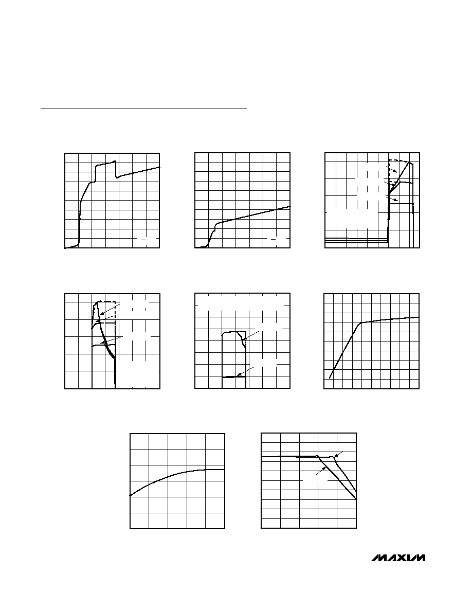
Typical Operating Characteristics
(V
DC
= 5V, R
SETI
= 2k
, V
BAT
= 3.6V, MAX8601 evaluation kit with thermal resistance of 50∞C/W. T
A
= +25∞C, unless otherwise noted.)
0
300
200
100
500
400
900
800
700
600
1000
0
2
4
6
8
10
12
14
SUPPLY CURRENT vs. INPUT VOLTAGE
MAX8600/01 toc01
INPUT VOLTAGE (V)
SUPPLY CURRENT (
µ
A)
V
EN
= 0V
0
300
200
100
500
400
900
800
700
600
1000
0
2
4
6
8
10
12
14
DISABLED SUPPLY CURRENT
vs. INPUT VOLTAGE
MAX8600/01 toc02
INPUT VOLTAGE (V)
SUPPLY CURRENT (
µ
A)
V
EN
= 5V
0
200
400
600
800
1000
0
1.0
0.5
1.5 2.0 2.5 3.0 3.5 4.0 4.5
CHARGE CURRENT
vs. BATTERY VOLTAGE
MAX8600/01 toc03
V
BAT
(V)
CHARGE CURRENT (mA)
DASHED DATA TAKEN
WITH PULSE TESTING TO
AVOID THERMAL LIMIT
R
SETI
= 1.5k
R
SETI
= 2k
R
SETI
= 3k
0
200
400
600
800
1000
0
2
4
6
8
10
12
14
CHARGE CURRENT
vs. DC VOLTAGE
MAX8600/01 toc04
V
DC
(V)
CHARGE CURRENT (mA)
R
SETI
= 1.5k
R
SETI
= 2k
R
SETI
= 3k
DASHED DATA
TAKEN WITH PULSE
TESTING TO AVOID
THERMAL LIMIT
0
200
100
400
300
700
600
500
800
0
4
2
6
8
10
12
14
CHARGE CURRENT vs. USB VOLTAGE
MAX8600/01 toc05
V
USB
(V)
CHARGE CURRENT (mA)
V
USEL
= 0V
V
USEL
= 5V
DASHED DATA TAKEN WITH
PULSE TESTING TO AVOID THERMAL LIMIT
0
200
100
400
300
600
500
700
900
800
1000
0
0.2 0.3 0.4
0.1
0.5 0.6 0.7
0.9
0.8
1.0
CHARGE CURRENT vs. INPUT
VOLTAGE HEADROOM
MAX8600/01 toc06
(V
IN
- V
BAT
) (V)
CHARGE CURRENT (mA)
4.180
4.190
4.185
4.200
4.195
4.205
4.210
-40
10
-15
35
60
85
BATTERY REGULATION
VOLTAGE vs. AMBIENT TEMPERATURE
MAX8600/01 toc07
T
A
(
∞C)
BATTERY REGULATION VOLTAGE (V)
0
300
200
100
400
500
600
700
800
900
1000
-40
10
-15
35
60
85
CHARGE CURRENT vs. AMBIENT
TEMPERATURE (750mA CHARGE)
MAX8600/01 toc08
T
A
(
∞C)
CHARGE CURRENT (mA)
V
BAT
= 4V
V
BAT
= 3.6V
MAX8600/MAX8601
Single-/Dual-Input 1-Cell Li+ Chargers with
OVP Protection and Programmable Charge Timer
_______________________________________________________________________________________
5
PIN
MAX8600
MAX8601
NAME
FUNCTION
1
1, 7
BAT
Battery Connection. The IC delivers charging current and monitors battery voltage using BAT.
Bypass BAT to GND with a 2.2µF or larger ceramic capacitor. Connect both BAT inputs
together externally (MAX8601). BAT is high impedance when the IC is disabled.
2
2
SETI
DC Charge-Current Programming Input. Connect a resistor from SETI to GND to set the
maximum charging current when using the DC input, the prequal current from either input, and
the CHG turn-off threshold.
3
3
THM
Thermistor Input. Connect a 10k
NTC thermistor, in close proximity to the battery, from THM
to ground to monitor the battery temperature. Connect THM to GND to disable the thermistor
functionality. The IC suspends charging when R
THM
is outside the hot and cold limits.
4
4
GND
Ground
5
5
CT
Timing Capacitor Input. Connect a capacitor from CT to GND to set the precharge timeout,
top-off time, and fast-charge timeout. Connect CT to GND to disable the timers.
6, 7, 9
--
N.C.
No Connection. Make no external circuit connection.
8
8
EN
Active-Low Enable Input. Drive low or connect EN to GND to enable the charger. Drive EN high
to disable the charger.
10
10
POK
Power-OK Monitor. POK is an open-drain output that pulls low when a valid charging source is
detected at either DC or USB (MAX8601). POK is high impedance when EN is high.
11
11
CHG
Charging-Status Output. CHG goes low when the battery is above 3V and being charged with
a current greater than 7.5% of the current programmed with R
SETI
. CHG is high impedance
when the charger is in prequal, top-off, or disabled.
Pin Description
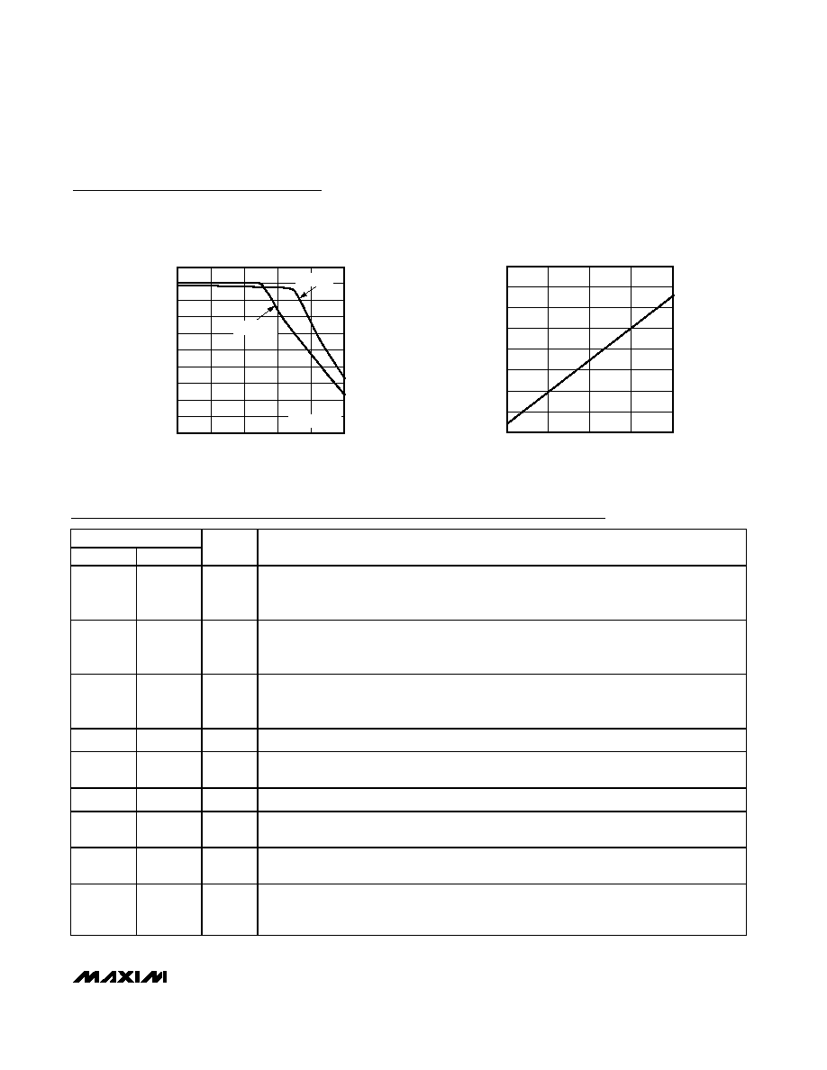
Typical Operating Characteristics (continued)
(V
DC
= 5V, R
SETI
= 2k
, V
BAT
= 3.6V, MAX8601 evaluation kit with thermal resistance of 50∞C/W. T
A
= +25∞C, unless otherwise noted.)
100
400
300
200
500
600
700
800
900
1000
1100
-40
10
-15
35
60
85
CHARGE CURRENT vs. AMBIENT
TEMPERATURE (1A CHARGE)
MAX8600/01 toc09
T
A
(
∞C)
CHARGE CURRENT (mA)
V
BAT
= 4V
V
BAT
= 3.6V
R
SETI
= 1.5k
0
100
200
300
400
500
600
700
800
0.010
0.045
0.080
0.115
0.150
FAST-CHARGE TIME vs. C
CT
MAX8600/01 toc10
C
CT
(
µF)
FAST-CHARGE TIME (MIN)