 | –≠–ª–µ–∫—Ç—Ä–æ–Ω–Ω—ã–π –∫–æ–º–ø–æ–Ω–µ–Ω—Ç: MAX9053 | –°–∫–∞—á–∞—Ç—å:  PDF PDF  ZIP ZIP |

General Description
The MAX9039≠MAX9043 and MAX9050≠MAX9053 fea-
ture combinations of low-power comparators and preci-
sion voltage references. Their operating voltage range
makes them ideal for both 3V and 5V systems. The
MAX9039/MAX9040/MAX9041/MAX9050/MAX9051
have a single comparator and reference consuming
only 40µA of supply current. The MAX9042/MAX9043/
MAX9052/MAX9053 have dual comparators and one
reference, and consume only 55µA of supply current.
Low-voltage operation and low supply current make
these devices ideal for battery-operated systems.
The comparators feature Rail-to-Rail
Æ
inputs and out-
puts, with a common-mode input voltage range that
extends 250mV beyond the supply rails. Input bias cur-
rent is typically 1.0pA, and input offset voltage is typi-
cally 0.5mV. Internal hysteresis ensures clean output
switching, even with slow-moving input signals. The
output stage features a unique design that limits supply
current surges while switching, virtually eliminating sup-
ply glitches typical of many other comparators. This
design also minimizes overall power consumption
under dynamic conditions. The comparator outputs
have rail-to-rail, push-pull output stages that sink and
source up to 8mA. The propagation delay is 400ns,
even with the low-operating supply current.
The reference output voltage is set to 1.23V in the
MAX9039, to 2.048V in the MAX9040≠MAX9043, and to
2.500V in the MAX9050≠MAX9053. The MAX9040≠
MAX9043 and the MAX9050≠MAX9053 are offered in
two grades: an A grade with 0.4% initial accuracy and
6ppm/∞C tempco, and a B grade with 1% initial accura-
cy and 100ppm/∞C tempco. The voltage references
feature a proprietary curvature-correction circuit and
laser-trimmed thin-film resistors. These series-mode ref-
erences can sink or source up to 500µA of load current.
Applications
Features
o Comparator + Precision Reference in UCSP/SOT23
o 2.5V to 5.5V Single-Supply Operation
(MAX9039≠MAX9043)
o Low Supply Current (MAX9039/MAX9040/
MAX9041/MAX9050/MAX9051)
40µA Quiescent
50µA with 100kHz Switching
o 400ns Propagation Delay
o Rail-to-Rail Inputs
o Rail-to-Rail Output Stage Sinks and Sources 8mA
o Internal ±3mV Hysteresis
o Voltage Reference Offers:
±0.4% (max) Initial Accuracy (A grade)
6ppm/∞C (typ) Temperature Coefficient (A grade)
Stable for 0 to 4.7nF Capacitive Loads
MAX9039≠MAX9043/MAX9050≠MAX9053
Micropower, Single-Supply, UCSP/SOT23
Comparator + Precision Reference ICs
________________________________________________________________ Maxim Integrated Products
1
19-1569; Rev 4; 10/02
Ordering Information
Rail-to-Rail is a registered trademark of Nippon Motorola, Ltd.
UCSP is a trademark of Maxim Integrated Products, Inc.
*UCSP reliability is integrally linked to the user's assembly
methods, circuit board material, and environment. Refer to the
UCSP Reliability section of this data sheet for more information.
Typical Operating Circuit and Functional Diagrams appear
at end of data sheet.
Ordering Information continued at end of data sheet.
Selector Guide appears at end of data sheet.
TOP VIEW (BUMPS ON BOTTOM)
TOP VIEW
V
EE
REF
IN+
1
5
V
CC
OUT
MAX9040
MAX9050
SOT23-5
2
3
4
IN-
V
CC
REF
V
EE
IN+
MAX9039
B3
OUT
B1
A3
A2
A1
B2
UCSP
Pin Configurations
Pin Configurations continued at end of data sheet.
For pricing, delivery, and ordering information, please contact Maxim/Dallas Direct! at
1-888-629-4642, or visit Maxim's website at www.maxim-ic.com.
PIN-
PACKAGE
6 UCSP-6
5 SOT23-5
6 SOT23-6
6 SOT23-6
8 SO
8 SO
5 SOT23-5
-40∞C to +85∞C
MAX9040AEUK-T
ADNW
-40∞C to +85∞C
-40∞C to +85∞C
-40∞C to +85∞C
-40∞C to +85∞C
-40∞C to +85∞C
-40∞C to +85∞C
TEMP RANGE
PART
MAX9039BEBT-T*
MAX9040BEUK-T
MAX9041AEUT-T
MAX9041BEUT-T
MAX9041AESA
MAX9041BESA
TOP
MARK
AAZ
ADNX
AAHF
AAHH
--
--
Precision Battery
Management
Window Comparators
IR Receivers
Level Translators
Digital Line Receivers

MAX9039≠MAX9043/MAX9050≠MAX9053
Micropower, Single-Supply, UCSP/SOT23
Comparator + Precision Reference ICs
2
_______________________________________________________________________________________
ABSOLUTE MAXIMUM RATINGS
ELECTRICAL CHARACTERISTICS--A Grade (0.4% Initial Accuracy)
(V
CC
= +5V, V
EE
= 0V, V
CM
= 0V, I
OUT
= 0A, I
REF
= 0A, T
A
= T
MIN
to T
MAX
, unless otherwise noted. Typical values are at
T
A
= +25∞C.) (Note 2)
Stresses beyond those listed under "Absolute Maximum Ratings" may cause permanent damage to the device. These are stress ratings only, and functional
operation of the device at these or any other conditions beyond those indicated in the operational sections of the specifications is not implied. Exposure to
absolute maximum rating conditions for extended periods may affect device reliability.
Supply Voltage (V
CC
to V
EE
) ....................................-0.3V to +6V
All Other Pins ...................................(V
EE
- 0.3V) to (V
CC
+ 0.3V)
Output Short-Circuit Duration
(OUT_, REF) ...............Indefinite Short Circuit to Either Supply
Continuous Power Dissipation (T
A
= +70∞C)
5-Pin SOT23 (derate 7.10mW/∞C above +70∞C)..........571mW
6-Bump UCSP (derate 3.9mW/∞C above +70∞C) ........308mW
6-Pin SOT23 (derate 8.70mW/∞C above +70∞C)..........696mW
8-Pin SO (derate 5.88mW/∞C above +70∞C)................471mW
8-Pin µMAX (derate 4.1mW/∞C above +70∞C) .............330mW
10-Pin µMAX (derate 5.6mW/∞C above +70∞C) ...........444mW
Operating Temperature Range ...........................-40∞C to +85∞C
Junction Temperature ......................................................+150∞C
Storage Temperature Range .............................-65∞C to +150∞C
Lead Temperature (soldering, 10s) .................................+300∞C
Bump Reflow Temperature (Note 1) ................................+235∞C
Note 1: This device is constructed using a unique set of packaging techniques that impose a limit on the thermal profile the device
can be exposed to during board-level solder attach and rework. This limit permits only the use of the solder profiles recom-
mended in the industry-standard specification, JEDEC 020A, paragraph 7.6, Table 3 for IR/VPR and Convection Packaging
Reflow. Preheating is required. Hand or wave soldering is not allowed.
PARAMETER
SYMBOL
CONDITIONS
MIN
TYP
MAX
UNITS
MAX9040≠MAX9043
2.5
5.5
Supply Voltage Range (Note 3)
V
CC
MAX9050≠MAX9053
2.7
5.5
V
V
CC
= 2.7V
47
67
MAX9040/MAX9041/
MAX9050/MAX9051
V
CC
= 5V
52
72
V
CC
= 2.7V
55
80
Supply Current
I
CC
MAX9042/MAX9043/
MAX9052/MAX9053
V
CC
= 5V
60
85
µA
COMPARATORS
T
A
= +25∞C
±0.5
±5.0
Input Offset Voltage (Note 4)
V
OS
Over entire
common-mode
range
T
A
= -40∞C to +85∞C
±7.0
mV
Input Hysteresis
V
HYST
±3.0
mV
Input Bias Current
(Notes 5, 6, 7)
I
B
Specified common-mode range
±0.001
±10.0
nA
Input Offset Current (Note 5)
I
OS
Specified common-mode range
±0.5
pA
T
A
= +25∞C
V
EE
-
0.25
V
CC
+
0.25
Common-Mode Voltage Range
(Notes 5, 8)
CMVR
T
A
= -40∞C to +85∞C
V
EE
V
CC
V
Common-Mode Rejection Ratio
(Note 5)
CMRR
Specified common-mode range
52
80
dB
MAX9040≠MAX9043, 2.5V
V
CC
5.5V
55
80
Power-Supply Rejection Ratio
PSRR
MAX9050≠MAX9053, 2.5V
V
CC
5.5V
55
80
dB
Input Capacitance (Note 5)
C
IN
2.5
pF
V
CC
= 5V
95
Output Short-Circuit Current
I
SC
V
OUT
=
V
EE
or V
CC
V
CC
= 2.7V
35
mA
V
CC
= 5V, I
SINK
= 8mA
0.2
0.55
Output Voltage Low
V
OL
V
CC
= 2.7V, I
SINK
= 3.5mA
0.15
0.4
V

MAX9039≠MAX9043/MAX9050≠MAX9053
Micropower, Single-Supply, UCSP/SOT23
Comparator + Precision Reference ICs
_______________________________________________________________________________________
3
ELECTRICAL CHARACTERISTICS--A Grade (0.4% Initial Accuracy) (continued)
(V
CC
= +5V, V
EE
= 0V, V
CM
= 0V, I
OUT
= 0A, I
REF
= 0A, T
A
= T
MIN
to T
MAX
, unless otherwise noted. Typical values are at
T
A
= +25∞C.) (Note 2)
ELECTRICAL CHARACTERISTICS--B Grade (1% Initial Accuracy)
(V
CC
= 5V, V
EE
= 0V, V
CM
= 0V, I
OUT
= 0A, I
REF
= 0A, T
A
= T
MIN
to T
MAX
, unless otherwise noted. Typical values are at T
A
= +25∞C.)
(Note 2)
PARAMETER
SYMBOL
CONDITIONS
MIN
TYP
MAX
UNITS
V
CC
= 5V, I
SOURCE
= 8mA
4.45
4.85
Output Voltage High
V
OH
V
CC
= 2.7V, I
SOURCE
= 3.5mA
2.3
2.55
V
C
L
= 15pF
40
C
L
= 50pF
50
Output Rise/Fall Times
t
R
/t
F
C
L
= 200pF
80
ns
50mV overdrive
450
Output Propagation Delay
(Note 9)
t
PD+/
t
PD-
C
L
= 15pF,
V
CC
= 2.7V
100mV overdrive
400
ns
Power-Up Time
t
PU
Time to V
OUT
valid logic state
20
µs
VOLTAGE REFERENCE
MAX9040≠MAX9043
2.040
2.048
2.056
Output Voltage
V
REF
T
A
= +25∞C
MAX9050≠MAX9053
2.490
2.500
2.510
V
µMAX/SO
6
30
Output Voltage Temperature
Coefficient (Note 10)
TCV
REF
SOT23
6
50
ppm/∞C
2.5V
V
CC
5.5V, MAX9040≠MAX9043
+50
+200
Line Regulation
V
REF
/
V
CC
2.7V
V
CC
5.5V, MAX9050≠MAX9053
+50
+200
µV/V
Sourcing. 0µA
I
REF
500µA
2
4
Load Regulation
V
REF
/
I
REF
Sinking, -500µA
I
REF
0µA
3.5
6
µV/µA
Output Short-Circuit Current
I
SC
V
REF
= V
EE
or V
CC
4
mA
Thermal Hysteresis (Note 11)
T
HYST
130
ppm
Long-Term Stability
1000h at T
A
= +25∞C
50
ppm
f = 0.1Hz to 10Hz
40
µV
P-P
Noise Voltage
E
OUT
f = 10Hz to 10kHz
105
µV
RMS
Ripple Rejection
V
REF
/
V
CC
V
CC
= 5V ±100mV, f = 120Hz
84
dB
Turn-On Settling Time
t
R
(V
REF
)
To V
REF
= 1% of final value
200
µs
Capacitive-Load Stability Range
(Note 7)
C
L
(V
REF
)
0
4.7
nF
PARAMETER
SYMBOL
CONDITIONS
MIN
TYP
MAX
UNITS
MAX9039≠MAX9043
2.5
5.5
Supply Voltage Range (Note 3)
V
CC
MAX9050≠MAX5053
2.7
5.5
V
V
CC
= 2.7V
40
MAX9039/MAX9040/
MAX9041/MAX9050/
MAX9051
V
CC
= 5.0V
45
100
V
CC
= 2.7V
55
Supply Current
I
CC
MAX9042/MAX9043/
MAX9052/MAX5053
V
CC
= 5.0V
60
130
µA
MAX9039≠MAX9043/MAX9050≠MAX9053
Micropower, Single-Supply, UCSP/SOT23
Comparator + Precision Reference ICs
4
_______________________________________________________________________________________
ELECTRICAL CHARACTERISTICS--B Grade (1% Initial Accuracy) (continued)
(V
CC
= 5V, V
EE
= 0V, V
CM
= 0V, I
OUT
= 0A, I
REF
= 0A, T
A
= T
MIN
to T
MAX
, unless otherwise noted. Typical values are at T
A
= +25∞C.)
(Note 2)
PARAMETER
SYMBOL
CONDITIONS
MIN
TYP
MAX
UNITS
COMPARATOR
Input Offset Voltage (Note 4)
V
OS
Over entire common-mode range
±1
±9.0
mV
Input Hysteresis
V
HYST
±3.0
mV
Input Bias Current (Notes 5, 6, 7)
I
B
Specified common-mode range
±0.001
±25.0
nA
Input Offset Current (Note 5)
I
OS
Specified common-mode range
±0.5
pA
Common-Mode Voltage Range
(Notes 5, 8)
CMVR
V
EE
V
CC
V
Common-Mode Rejection Ratio
(Note 5)
CMRR
Specified common-mode range
52
80
dB
MAX9039≠MAX9043, 2.5V
V
CC
5.5V
55
80
Power-Supply Rejection Ratio
PSRR
MAX9050≠MAX9053, 2.7V
V
CC
5.5V
55
80
dB
Input Capacitance (Note 5)
C
IN
2.5
pF
V
CC
= 5V
95
Output Short-Circuit Current
I
SC
V
OUT
= V
EE
or V
CC
V
CC
= 2.7V
35
mA
V
CC
= 5V, I
SINK
= 8mA
0.2
0.55
Output Voltage Low
V
OL
V
CC
= 2.7V, I
SINK
= 3.5mA
0.15
V
V
CC
= 5V, I
SOURCE
= 8mA
4.45
4.85
Output Voltage High
V
OH
V
CC
= 2.7V, I
SOURCE
= 3.5mA
2.55
V
C
L
= 15pF
40
C
L
= 50pF
50
Output Rise/Fall Times
t
R
/t
F
C
L
= 200pF
80
ns
50mV overdrive
450
Output Propagation Delay
(Note 9)
t
PD+
/t
PD-
C
L
= 15pF,
V
CC
= 2.7V
100mV overdrive
400
ns
Power-Up Time
t
PU
Time to V
OUT
valid logic state
20
µs
VOLTAGE REFERENCE
MAX9039
1.218
1.230
1.242
MAX9040≠MAX9043
2.028
2.048
2.068
Output Voltage
V
REF
T
A
= +25∞C
MAX9050≠MAX9053
2.475
2.500
2.525
V
Output Voltage Temperature
Coefficient (Note 10)
TCV
REF
20
100
ppm/∞C
MAX9039≠MAX9043
+50
+200
Line Regulation
V
REF
/
V
CC
2.5V
V
CC
5.5V
MAX9050≠MAX9053
+50
+200
µV/V
Sourcing: 0µA
I
REF
500µA
2
4
Load Regulation
V
REF
/
I
REF
Sinking: -500µA
I
REF
0µA
3.5
6
µV/µA
Output Short-Circuit Current
I
SC
V
REF
= V
EE
or V
CC
4
mA
Thermal Hysteresis (Note 11)
T
HYST
130
ppm
Long-Term Stability
1000h at T
A
= +25∞C
100
ppm
f = 0.1Hz to 10Hz
40
µV
P-P
Noise Voltage
E
OUT
f = 10Hz to 10kHz
105
µV
RMS
MAX9039≠MAX9043/MAX9050≠MAX9053
Micropower, Single-Supply, UCSP/SOT23
Comparator + Precision Reference ICs
_______________________________________________________________________________________
5
ELECTRICAL CHARACTERISTICS--B Grade (1% Initial Accuracy) (continued)
(V
CC
= 5V, V
EE
= 0V, V
CM
= 0V, I
OUT
= 0A, I
REF
= 0A, T
A
= T
MIN
to T
MAX
, unless otherwise noted. Typical values are at T
A
= +25∞C.)
(Note 2)
Note 2: All devices are 100% production tested at T
A
= +25∞C. Limits over the extended temperature range are guaranteed by
design.
Note 3: Supply voltage range guaranteed by PSRR test on comparator and line regulation of REF.
Note 4: V
OS
is defined as the center of the input-referred hysteresis band.
Note 5: For the comparators with the inverting input (IN-) uncommitted.
Note 6: Input bias current is the average of the inverting and noninverting input bias currents.
Note 7: Not production tested. Guaranteed by design.
Note 8: Guaranteed by CMRR test.
Note 9: V
OVERDRIVE
is beyond the offset and hysteresis determined trip point.
Note 10: Temperature coefficient is measured by the box method; i.e., the maximum
V
REF
is divided by the maximum
T.
Note 11: Thermal hysteresis is defined as the change in V
REF
at +25∞C before and after cycling the device from T
MIN
to T
MAX
.
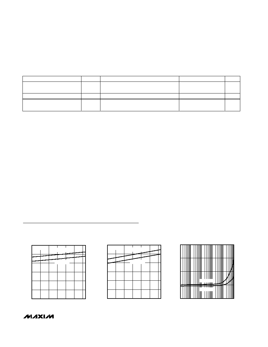
Typical Operating Characteristics
(V
CC
= 5V, V
EE
= 0V, V
CM
= 0V, I
OUT
= 0A, I
REF
= 0A, T
A
= +25∞C, unless otherwise noted.)
0
10
30
20
50
40
60
-40
0
-20
20
40
60
80
MAX9039/MAX9040/MAX9041/MAX9050/MAX9051
SUPPLY CURRENT vs. TEMPERATURE
MAX9039/43/50-53 toc01
TEMPERATURE (
∞C)
SUPPLY CURRENT (
µ
A)
V
CC
= 5.0V
V
IN+
>
V
IN-
V
CC
= 2.7V
0
10
30
20
50
40
60
-40
0
-20
20
40
60
80
MAX9042/MAX9043/MAX9052/MAX9053
SUPPLY CURRENT vs. TEMPERATURE
MAX9039/43/50-53 toc02
TEMPERATURE (
∞C)
SUPPLY CURRENT (
µ
A)
V
CC
= 5.0V
V
IN+
>
V
IN-
V
CC
= 2.7V
0.01
0.1
1
10
100
1000
200
150
100
50
0
MAX9039/MAX9040/MAX9041/MAX9050/MAX9051
SUPPLY CURRENT vs. SWITCHING FREQUENCY
MAX9039/43/50-53 toc03
SWITCHING FREQUENCY (kHz)
SUPPLY CURRENT (
µ
A)
V
CC
= 5.0V
V
CC
= 2.7V
PARAMETER
SYMBOL
CONDITIONS
MIN
TYP
MAX
UNITS
Ripple Rejection
V
REF
/
V
CC
V
CC
= 5V ±100mV, f = 120Hz
84
dB
Turn-On Settling Time
t
R
(V
REF
)
To V
REF
= 1% of final value
200
µs
Capacitive Load Stability Range
(Note 7)
C
L
(V
REF
)
0
4.7
nF