 | –≠–ª–µ–∫—Ç—Ä–æ–Ω–Ω—ã–π –∫–æ–º–ø–æ–Ω–µ–Ω—Ç: 1A184A | –°–∫–∞—á–∞—Ç—å:  PDF PDF  ZIP ZIP |

PRODUCT INFORMATION
Europe: Tel (46) 8 58 02 45 00
Fax (46) 8 58 02 01 10
Tel (44) 1291 436180
Fax (44) 1291 436771
America: Tel 1-800-96MITEL Fax (613) 592-6909
Asia:
Tel (65) 293 5312
Fax (65) 293 8527
0.6
14
ÿ1.5
ÿ4.7
3.7
0.4
5.4
2.5
CASE
ANODE
CATHODE
BOTTOM VIEW
The anode is in electrical contact with the case.
TO-46 Package With Lens
All dimensions in mm
Optical and Electrical Characteristics
(25∞ C Case Temperature)
Thermal Characteristics
870
nm
1A184A
High-Performance LED
FM Video
Absolute Maximum Ratings
Note 1: Measured at the exit of 100 meters of fiber.
PARAMETER
SYMBOL
MIN.
TYP.
MAX.
UNIT
Thermal Resistance - Infinite Heat Sink
Rthjc
100 ∞C/W
Thermal Resistance - No Heat Sink
Rthja
400
∞C/W
Temperature Coefficient - Optical Power
dP/dTj
-0.6
%/∞C
Temperature Coefficient -Wavelength
d /dTj
0.3
nm/∞C
PARAMETER
SYMBOL
LIMIT
Storage Temperature
Tstg
-55 to + 125∞ C
Operating Temperature
see (derating: Fig.4)
Top
-55 to +125∞ C
Electrical Power Dissipation
(derating: Fig.4)
Ptot
250 mW
Continuous Forward Current
(f 10 kHz)
I
F
110 mA
Peak Forward Current
(duty cycle 50%s, f 1 MHz)
I
FRM
180 mA
Reverse Voltage
V
R
1.5 V
Soldering Temperature
(2mm from the case for 10sec)
Tsld
260∞ C
Fiber:
50/125µm
Graded
Index
NA=0.20
PARAMETER
SYMBOL
MIN.
TYP.
MAX.
UNIT
TEST CONDITION
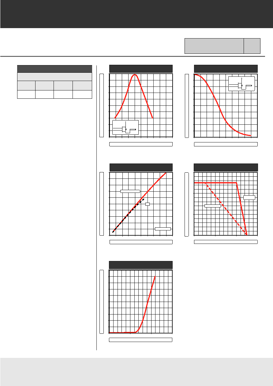
Fiber-Coupled Power
(Fig. 1,2,&3) (Table 1)
Pfiber
40
55
µW
I
F
=100 mA
Rise and Fall Time
tr,tf
2.5
3
ns
I
F
=100 mA
(10-90%)
(no bias)
Bandwidth
fc
140
MHz
I
F
=100 mA
(3 dBel)
Harmonic Distortion
-H
2
40
dB
I
F
=80 mA
(nonlinearity)
m= 0.8
-H
3
45
dB
f=10 MHz
Peak Wavelength
p
850
870
890
nm
I
F
=100 mA
Spectral Width
(FWHM)
60
nm
I
F
=100 mA
Forward Voltage
(Fig.5)
V
F
1.8
2.2
V
I
F
=100 mA
Reverse Current
I
R
20
µA
V
R
=1V
Capacitance
C
250
pF
V
R
= 0V, f=1 MHz
The low harmonic distortion makes
this device ideal for subcarrier FM
video applications. Video transmis-
sion can be accomplished with mini-
mum distortion. The double-lens
optical system provides for optimum
coupling of power into the fiber.
11705.12 1995-09-01
CORE DIAMETER/CLADDING DIAMETER
NUMERICAL APERTURE
50/125 µm
62.5/125 µm
100/140 µm
200/230 µm
0.20
0.275
0.29
0.37
870
nm
1A184A
High-Performance LED
Table 1
Typical Fiber-Coupled Power
55 µW
150 µW
300 µW
390 µW
z - AXIAL DISPLACEMENT OF FIBER
RELATIVE FIBER-COUPLED POWER
0
20
40
60
80
100
%
0.5
1.0
1.5
2.0
2.5 3.0 mm
r
r = opt.
ÿc = 50 µm
z
FIGURE 1
0
20
40
60
80
100
%
0
20
40
60
80
100 m
RELATIVE FIBER-COUPLED POWER
r
z = opt.
ÿc = 50 µm
z
r - RADIAL DISPLACEMENT OF FIBER
RELATIVE FIBER-COUPLED POWER
FIGURE 2
0
20
40
60
80
100
%
0
40
80
120
160
200
mA
RELATIVE FIBER-COUPLED POWER
FORWARD CURRENT
50% DUTY CYCLE
DC
HEAT SINKED
FIGURE 3
FORWARD VOLTAGE
FORWARD CURRENT
mA
200
100
0
0
1
2
3
V
FIGURE 5
mW
300
200
100
0
0
50
100
150°C
NO HEAT SINK
OPERATING TEMPERATURE
MAX. ELECTRICAL POWER DISSIPATION
FIGURE 4
INFINITE
HEAT SINK
3.3000
5.6000
80,000
10,2500
R 1.00
0.5000
10.3000
20.8200
4.9500
0.5000
4.5000
5.0800
3.6450
Clip for SC-2A

10.25
0.50
10.30
10.70
4.50
3.65
5.08
0.85
0.50
4.95
Clip for Pigtail-3A

PRODUCT INFORMATION
Europe: Tel (46) 8 58 02 45 00
Fax (46) 8 58 02 01 10
Tel (44) 1291 436180
Fax (44) 1291 436771
America: Tel 1-800-96MITEL Fax (613) 592-6909
Asia:
Tel (65) 293 5312
Fax (65) 293 8527
103326 1994-09-20
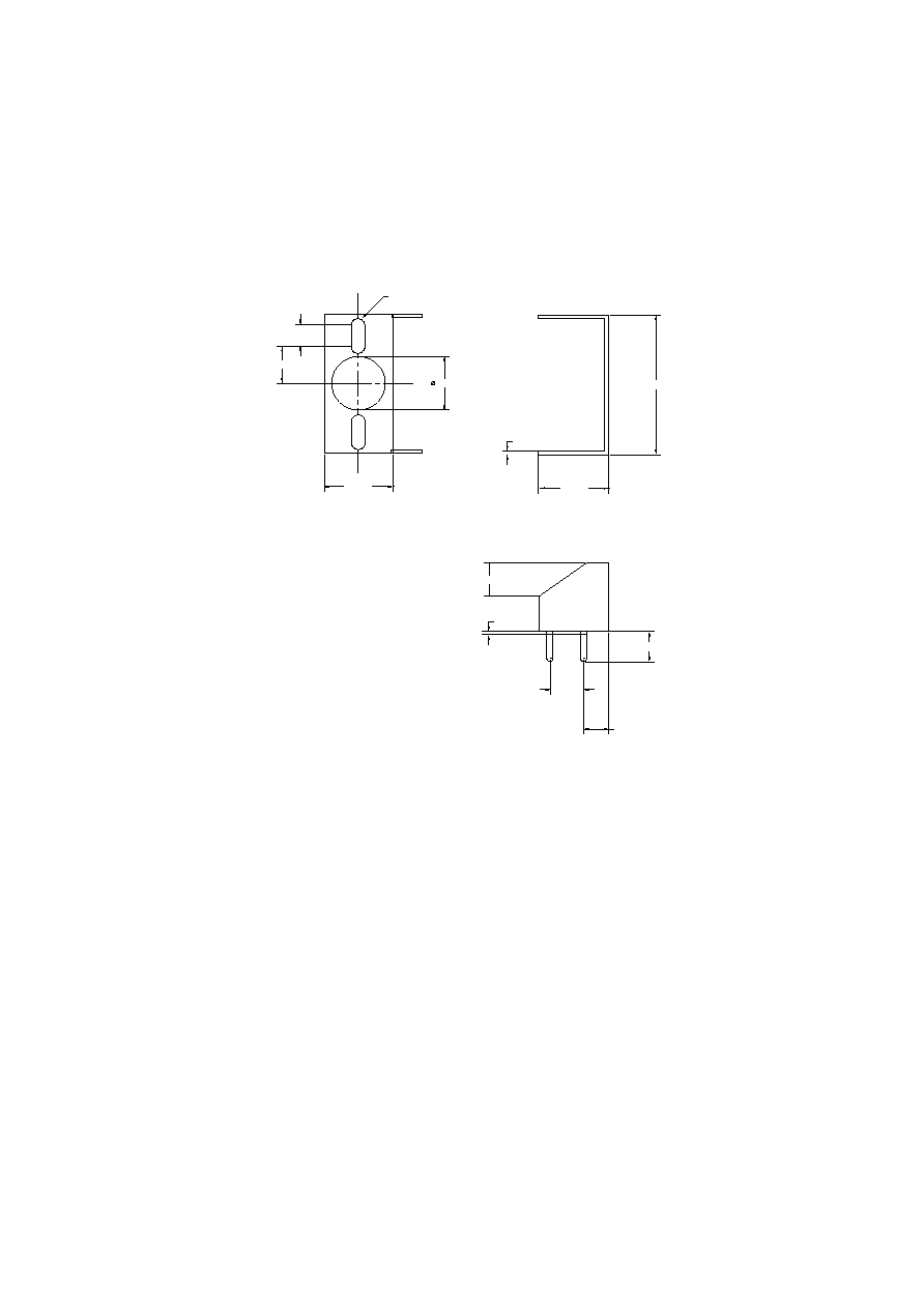
ST-2A
Package
Emitter or Detector in ST
Æ
Package
Mitel emitters and detectors can be
provided in this low-profile ST
Æ
package. The device is electrically
isolated from the ST
Æ
receptacle to
facilitate electrical connection. And
optimum fiber-coupled power or
responsivity is ensured by active
alignment against the fiber.
Mechanical Outline of Diode in ST-2A Housing
(ST is a registered trademark of AT&T)
All Dimensions in mm
*
The fiber-coupled power/responsivity is guaranteed to meet the LED/PIN data sheet - provided a ferrule meeting this specification is used.
Absolute Maximum Ratings
Thermal Characteristics
Note 2: Add Rthjc for emitter or detector to estimate the total thermal resistance.
Note 1: Temperature range can be extended to -55∞ to +125∞C on request.
12.7
MARKING SIDE
SLOT SIDE
9.5
7.89
2-56 UNC - 2B
max.0.5
min.12
20.1
3.9
5.4
7.6
3/8"-32 UNEF
0.006
FIBER
END
ÿ2.5
ÿ2.502
+0.01
0
+0
-0.004
MATING FERRULE
*
(not included)
PARAMETER
SYMBOL
LIMIT
Operating & Storage Temperature
Tstg, Top
-40 to + 85 C
ST-2A (Note 1)
PARAMETER
SYMBOL
MIN.
TYP.
MAX.
UNIT
Thermal Resistance - Infinite Heat Sink
Rthcc
40
C/W
(Note 2)
Thermal Resistance - No Heat Sink
Rthca
200
C/W
(Note 2)
Thermal Resistance - On PC Board
Rthca
80
C/W
(Note 2)