 | –≠–ª–µ–∫—Ç—Ä–æ–Ω–Ω—ã–π –∫–æ–º–ø–æ–Ω–µ–Ω—Ç: MH88634 | –°–∫–∞—á–∞—Ç—å:  PDF PDF  ZIP ZIP |
2-253
Æ
Features
∑
Loop Start Trunk Interface
∑
600 ohm input impedance, -2 variant
∑
Line state detection outputs: forward loop,
reverse loop, ringing voltage, switch hook
On-hook reception
∑
Transformerless 2W to 4W conversion
∑
One loop start relay driver
∑
+/- 5V operation
∑
Small footprint area (<4.75cm
2
)
Applications
Interface to Central Office for:
∑
PABX
∑
Key Telephone Systems
∑
Channel Bank
∑
Voice Mail
∑
Terminal Equipment
∑
Digital Loop Carrier
∑
Optical Multiplexer
Description
The Mitel MH88634 Central Office Trunk Interface
circuit provides a complete audio and signalling link
between audio switching equipment and a central
office. The functions provided by the MH88634
include 2-4 Wire conversion, 600 ohm input
impedance and network balance. The device is
fabricated as a thick film hybrid incorporating various
technologies for optimum circuit design and very
high reliability.
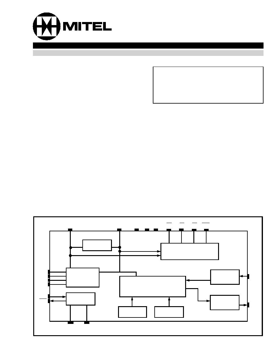
Figure 1 - Functional Block Diagram
Status
Detection
Transmit
Gain
2-4 Wire Hybrid
Dummy
Ringer
Loop
Termination
Loop Relay
Driver
Impedance
Matching
Network
Balance
XLA
XLB
XLC
XLD
LRC
LRD
VRLY RGND
RING
TIP
RV FL RL SHK
VDD VEE AGND
Rx
Tx
Receive
Gain
ISSUE 2
April 1995
Ordering Information
MH88634-2 21 Pin SIL Package
0
∞
C to 70
∞
C
MH88634
Central Office Interface Circuit
Preliminary Information
2-254
MH88634
Preliminary Information
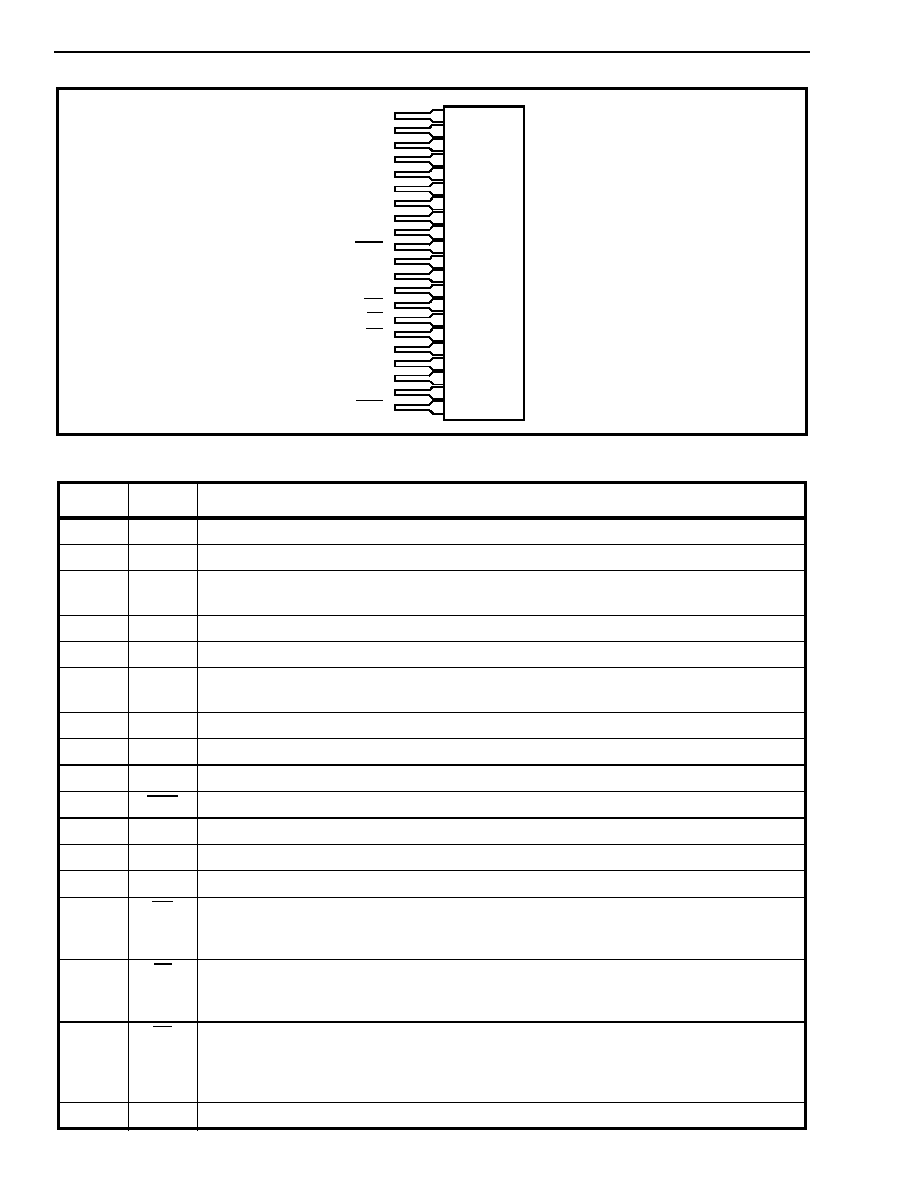
Figure 2 - Pin Connections
Pin Description
Pin #
Name
Description
1
TIP
Tip Lead: Connects to the "Tip" lead of the central office
2
RING
Ring Lead: Connects to the "Ring" lead of the central office
3
XLA
Loop Relay Contact A:. Connects to XLB through the Loop relay (K1) contacts when the
relay is activated. This operates the internal active termination circuitry.
4
XLD
Loop Relay Contact D: See XLC for description
5
XLB
Loop Relay Contact B: See XLA for description
6
XLC
Loop Relay Contact C: Connects to XLD through the loop relay (K1) contacts when the
relay is activated. This operates the internal active termination circuitry.
7
IC
Internal Connection: This pin is internally connected and must be left open.
8
IC
Internal Connection.: This pin is internally connected and must be left open.
9
IC
Internal Connection: This pin is internally connected and must be left open.
10
SHK
Switch Hook (Output). A logic low indicates either forward or reverse loop current.
11
Rx
Receive (Input): 4-Wire ground (AGND) referenced audio input.
12
VEE
Negative Supply Voltage. -5V
13
Tx
Transmit (Output). 4-Wire ground (AGND) referenced audio output.
14
RV
Ring Voltage Detect (Output). A logic low indicates that ringing voltage is across the Tip
and Ring leads. Note that this output toggles at the ringing cadence and not at the ringing
frequency.
15
FL
Forward Loop Detect (Output): In the on-hook state, a logic low output indicates that
forward loop battery is present. In the off-hook state, a logic low indicates that forward loop
current is present.
16
RL
Reverse Loop Detect (Output). In the on-hook state, a logic low output indicates that
reverse loop battery is present. In the off-hook state, a logic low output indicates that
reverse loop current is present. Reverse loop refers to the Tip lead negative respect to the
Ring Lead.
17
VDD
Positive Supply Voltage: +5V
TIP
RING
XLA
XLB
XLC
IC
IC
IC
SHK
Rx
VEE
Tx
RV
FL
RL
VDD
AGND
LRC
VRLY
LRD
XLD
1
2
3
4
5
6
7
8
9
10
11
12
13
14
15
16
17
18
19
20
21

2-255
Preliminary Information
MH88634
18
AGND
Analog Ground. 4-wire ground. Connected to system ground
19
LRC
Loop Relay Control (Input): A logic high activates the Loop Relay Driver output (LRD).
The Loop Relay activates internal circuitry which provides a DC termination across Tip and
Ring. Used for line seizure and dial pulsing.
20
VRLY
Relay Positive Supply Voltage. Typically +5V. Connects to the relay coil and the relay
supply voltage
21
LRD
Loop Relay Drive (Output). Connects to the Loop Relay coil. A logic low activates the
relay. An internal clamp diode from VRLY to LRD is provided.
Pin Description (Continued)
Pin #
Name
Description
Functional Description
The MH88634 is a COIC (Central Office Interface
Circuit) used to interface the Central Office 2-Wire
analog trunks. The COIC provides a Loop Start
interface function.
Incoming analog (voiceband) signals from the 2-Wire
circuit are applied differentially across Tip and Ring
the output of which is applied to the 2 to 4 wire
converter with a fixed gain to the Tx output.
The outgoing analog signals are applied to Rx. The
audio signals undergo 4 to 2 wire conversion with a
fixed gain, and are differentially applied to Tip and
Ring.
DC Loop Termination
The line is provided with an active DC load
termination when a logic high is applied to the LRC
(Loop Start Relay) input. The termination is similar to
a DC resistance of less than 275 ohms. An external
relay is used to activate internal circuitry which
switches the termination in and out of the loop. This
is used for both seizing the line as well as generating
dial pulses.
Supervision Features
The supervision circuitry provides, the signally status
outputs. The ringing voltage, forward current,
reverse current and switch hook. Ringing Voltage
detect - the RV output provides a logic low when
ringing voltage is detected. This sector includes a
ringing filter which ensures that the output toggles at
the ringing cadence and not at the ringing frequency.
Typically, this output goes low 50ms after the ringing
voltage is applied and remains low for 50ms after
ringing voltage is removed.
Forward loop and reverse loop detect - the FL output
provides a logic low when either forward loop battery
or forward loop current is detected (ring lead voltage
negative with respect to tip lead). The RL output
provides a logic low when either reverse loop battery
or reverse loop current is detected (tip lead voltage
negative with respect to ring lead)
SHK output is active if either forward loop or reverse
loop current is detected.
Line Impedance
The input impedance of the MH88634-2 is 600 ohms.
The network balance is also set at 600 ohms to
maximize the Transhybrid Balance.
Transmit and Receive Gain
Transmit Gain (Tip-Ring) is set at 0dB and Receive
Gain (Rx to Tip-Ring) is set at -2dB.
2-256
MH88634
Preliminary Information
Absolute Maximum Ratings*
Voltages are with respect to AGND
* Exceeding these values may cause permanent damage. Functional operation under these conditions is not implied.
Recommended Operating Conditions
* Exceeding these values may cause permanent damage. Functional operation under these conditions is not implied.
DC Electrical Characteristics
DC Electrical Characteristics are over recommended operating conditions unless otherwise stated.
* Typical figures are at 25∞C with nominally +5V supplies and are for design use only.
Parameters
Sym
Min
Max
Units
1
DC Supply Voltages
V
BAT
V
DD
V
EE
0
-0.3
0.3
-60
7
-7
V
V
V
2
DC Ring Relay Voltage
V
RLY
-0.3
7
V
3
Storage Temperature
T
S
-55
+125
∞C
Parameters
Symbol
Min
Typ*
Max
Units
Comments
1
DC Supply Voltages
V
DD
V
EE
4.75
-4.75
5.0
-5.0
5.25
-5.25
V
V
2
DC Ring Relay Voltage
V
RLY
5.0
15
V
3
Operating Temperature
T
OP
0
70
∞C
Characteristics
Sym
Min
Typ*
Max
Units
Test Conditions
1
Supply Current
I
DD
I
EE
13
13
mA
mA
2
Power Consumption
PC
137
mW
V
BAT
not connected
3
FL
RL
SHK
RV
Low Level Output Voltage
High Level Output Voltage
V
OL
V
OH
-.3
3.7
0.5
5.25
V
V
I
OL
= 4mA
I
OH
= 100
µ
A
4
LRD
Sink Current, Relay to V
DD
Clamp Diode Current
I
OL
I
CD
100
150
mA
mA
V
OL
= 0.35V not
continuous
5
LRC
Low Level Input Voltage
High Level Input Voltage
V
IL
V
IH
2.0
0.8
V
V
6
High Level Input Current
Low Level Input Current
I
IH
V
IH
40
40
µ
A
µ
A
V
IH
= 5.0V

2-257
Preliminary Information
MH88634
Loop Electrical Characteristics*
* DC Electrical Characteristics are over recommended operating conditions unless otherwise stated.
Typical figures are at 25∞C and are for design aid only.
AC Electrical Characteristics *
* AC Electrical Characteristics are over recommended operating conditions unless otherwise stated.
Typical figures are at 25∞C and are for design aid only.
Characteristics
Symbol
Min
Typ
Max
Units
Test Conditions
1
Ringing Voltage
VR
40
90
110
V
rms
2
Ringing Frequency
16
20
33
Hz
3
Ringer Equivalence Number
REN
0.5
1
2
Dummy ringer is 17K in
series with 330nF.
Type A ringing
4
Operating Loop Current
16
70
mA
5
Off-Hook DC Resistance
270
280
@ 20mA
6
Leakage Current (Tip-Ring to
AGND)
10
mA
@ 1000Vac
7
FL Threshold
Tip-Ring (On-hook)
Tip-ring Current (Off-Hook)
+30
+10
+40
15
Vdc
mA
LRC = 0v
LRC = 5V
8
RL Threshold
Tip-Ring (On-Hook)
Tip-Ring (Off-Hook)
-30
-8
-40
-15
Vdc
mA
LRC = 0v
LRC = 5V
Characteristics
Symbol
Min
Typ
Max
Units
Test
Conditions
1
2-wire Input Impedance (-2
variant)
Z
in
600
2
Return Loss at 2-wire
(Zin = Ref = 600)
RL
20
dB
200-3400 Hz
3
Longitudinal to Metallic
Balance
58
58
53
dB
200Hz
1000Hz
3.4kHz
4
Transhybrid Loss
THL
20
dB
200-3400Hz
5
Gain (voltage) 2 wire to Tx
0
d
1024Hz
6
Gain (Voltage)
Rx to 2 wire
-2
dB
Spec Freq
7
Input impedance at Rx
10
k
8
Output impedance at Rx
5
9
Signal Overload Level
at 2-wire output
at Tx
4.0
0.95
dBm
Vrms
% THD < 5%
Ref 600
@ 20mA
10
Total Harmonic Distortion
at 2-wire output
at Tx
THD
1.0
1.0
%
%
Input 0.5V, 1kHz @ Rx
Input 0.5V, 1kHz @
Tip-Ring
11
Idle Channel Noise
at 2-Wire
at Tx
NC
15
15
dBrnC
12
Power Supply Rejection Ratio
at 2-wire and Tx
V
DD
V
EE
PSRR
25 dB
25 dB
dB
dB
Ripple 0.1V, 1kHz
2-258
MH88634
Preliminary Information
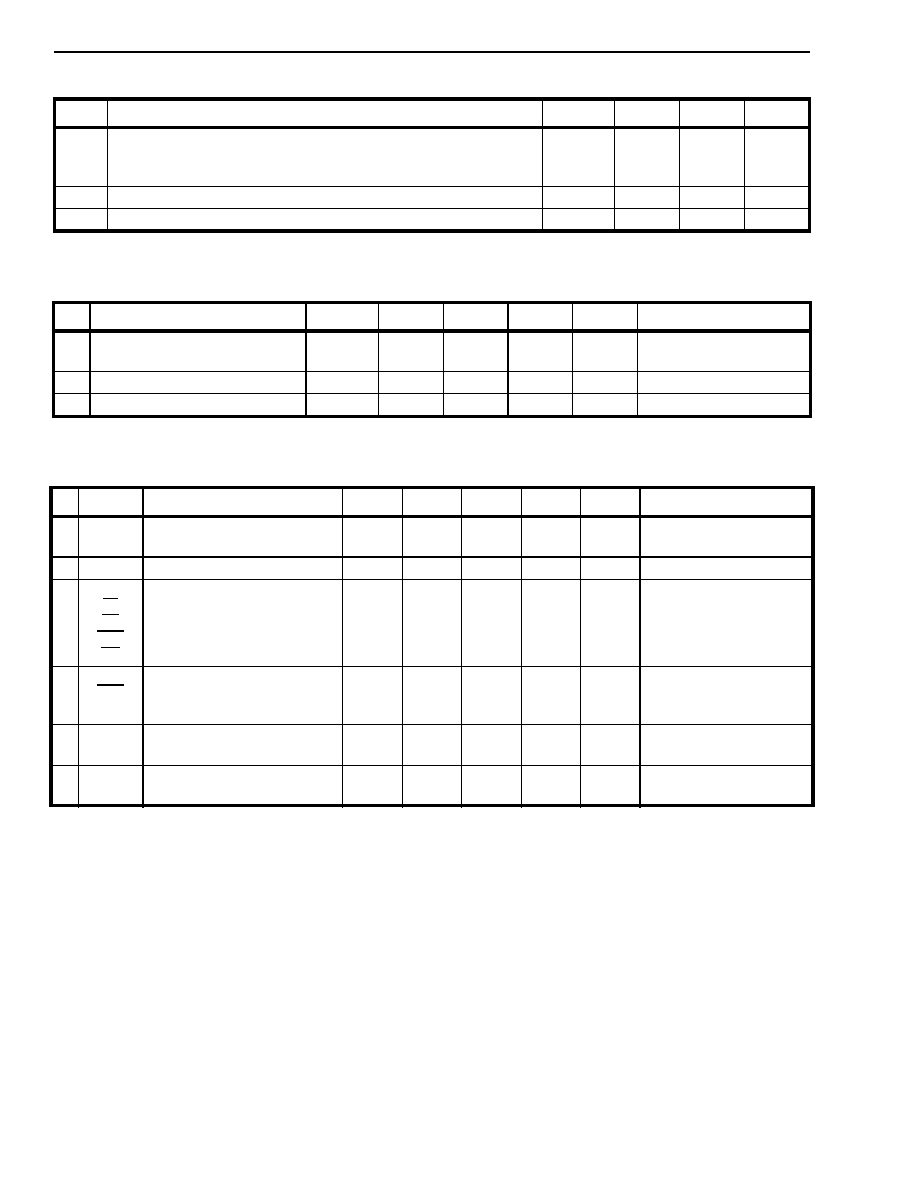
Figure 3 - Mechanical Data
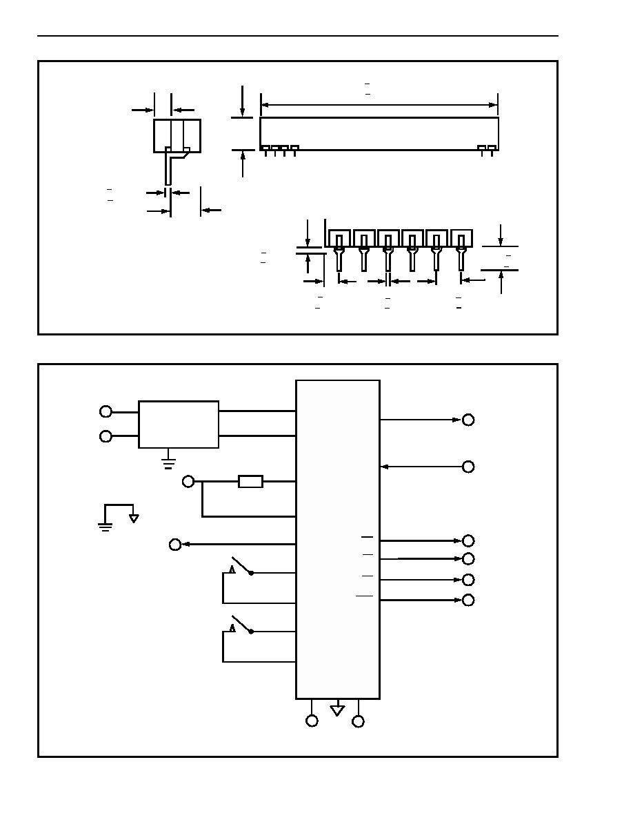
Figure 4 - Typical LS-GS Application Circuit
2.10 + 0.040
(53.3 + 1.0)
0.56 Max
(14.2 Max)
0.27 Max
(6.9 Max)
0.010 + 0.002
(0.25 + 0.05)
0.080 Max
(2.0 Max)
Side View
*
0.05 + 0.01
(1.3 + 0.5)
*
*
*
0.05 + 0.02
(1.225 + 0.05)
0.020 + 0.005
(0.51 + 0.13)
0.100 + 0.010
(2.54 + 0.26)
0.18 + 0.02
(4.6 + 0.5)
Notes:
1) Not to scale
2) Dimensions in inches).
3) (Dimensions in millimetres).
*Dimensions to centre of pin &
tolerance non accumulative.
MH88634
Audio Out
Audio In
Ring Detect
Forward Loop
Reverse Loop
Switch Hook
-5V
+5V
K1
K1
Protection
Circuit
Tip
Ring
Loop Relay Control
Tip
Ring
LRD
VRLY
LRC
XLA
XLB
XLC
XLD
VDD
AGND
VEE
RL
FL
RV
RX
TX
NOTES
:
1) See Figure 5 for
Protection Circuit.
2) K1 Electro Mechanical
2 form A.
SHK
+5V
K1
2-259
Preliminary Information
MH88634
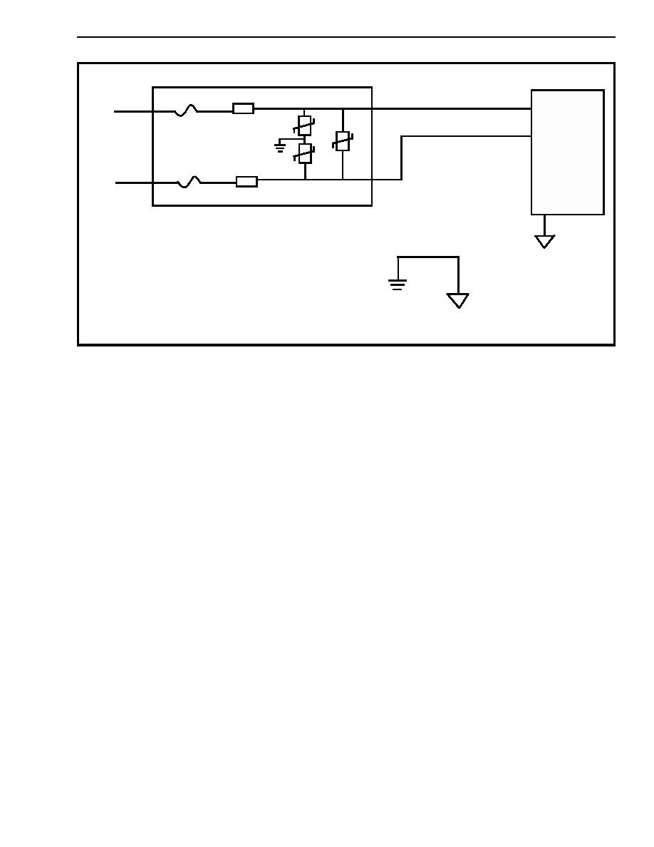
Figure 5 - External Application Circuit
Protection Circuit
R1
RV1
RV2
RV3
TIP
RING
AGND
RING
F2
F1
R2
MH88634
NOTES
1) F1, F2 are 1 AMP 250 VAC Slow-blow fuse
e.g. Littlefuse 230 2AG
2) R1, 22.4W, 5% 1/2W, 100V Flame Rated
resistor e.g., Allen Bradley EB24G5-L05
3) RV1, 2, 3 250 VAC 351 Metal Oxide Varistor
e.g. OHIZUMI, 025ONC 12D
TIP

MH88634
Preliminary Information
2-260
Notes: