Order this document
by MC68HC11A8TS/D
© MOTOROLA INC., 1991, 1996
This document contains information on a new product. Specifications and information herein are subject to change without notice.
MOTOROLA
SEMICONDUCTOR
TECHNICAL DATA
MC68HC11A8
MC68HC11A1
MC68HC11A0
Technical Summary
8-Bit Microcontrollers
1 Introduction
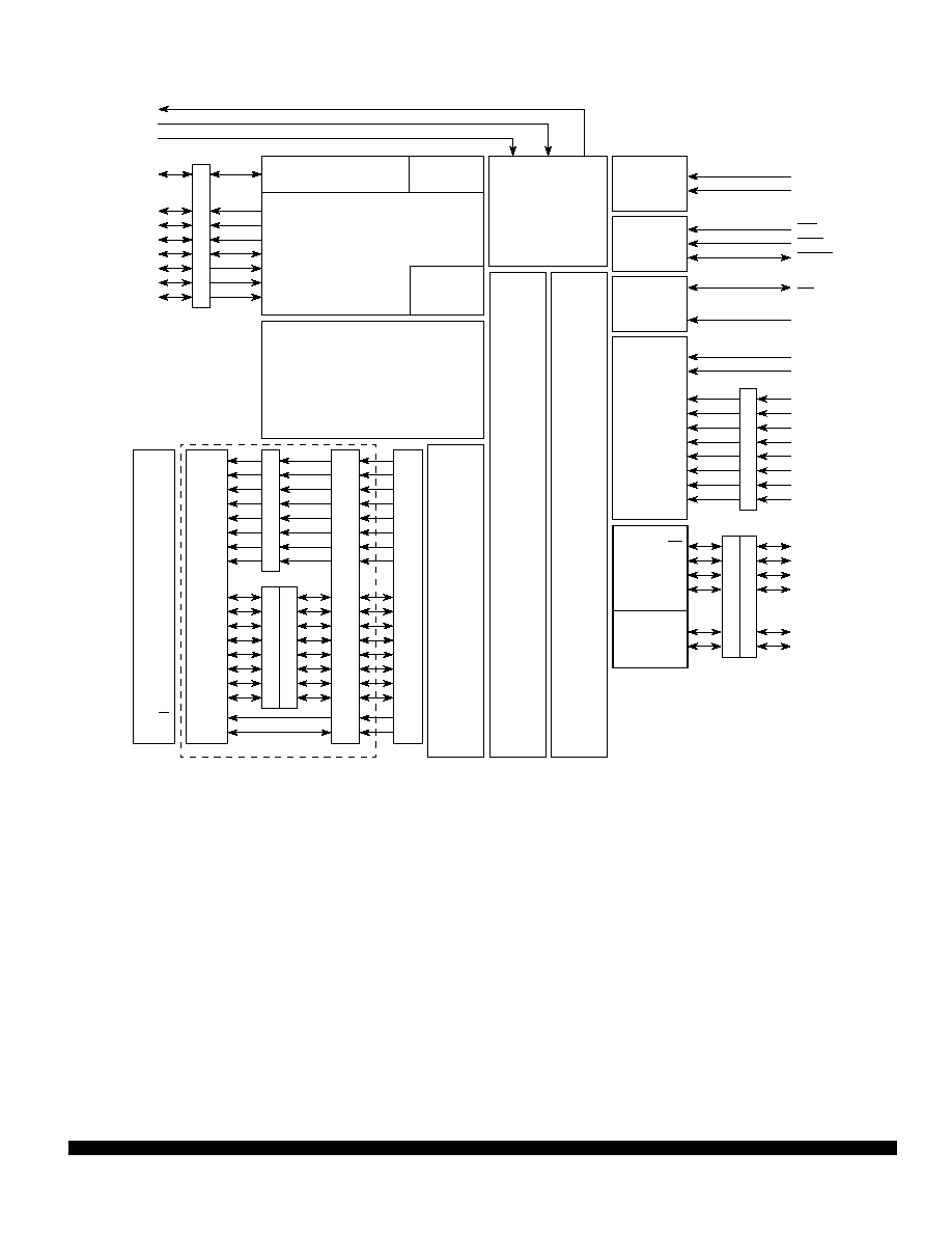
The MC68HC11A8, MC68HC11A1, and MC68HC11A0 high-performance microcontroller units (MCUs)
are based on the M68HC11 Family. These high speed, low power consumption chips have multiplexed
buses and a fully static design. The chips can operate at frequencies from 3 MHz to dc. The three MCUs
are created from the same masks; the only differences are the value stored in the CONFIG register, and
whether or not the ROM or EEPROM is tested and guaranteed.
For detailed information about specific characteristics of these MCUs, refer to the
M68HC11 Reference
Manual
(M68HC11RM/AD).
1.1 Features
∑ M68HC11 CPU
∑ Power Saving STOP and WAIT Modes
∑ 8 Kbytes ROM
∑ 512 Bytes of On-Chip EEPROM
∑ 256 Bytes of On-Chip RAM (All Saved During Standby)
∑ 16-Bit Timer System
-- 3 Input Capture Channels
-- 5 Output Compare Channels
∑ 8-Bit Pulse Accumulator
∑ Real-Time Interrupt Circuit
∑ Computer Operating Properly (COP) Watchdog System
∑ Synchronous Serial Peripheral Interface (SPI)
∑ Asynchronous Nonreturn to Zero (NRZ) Serial Communications Interface (SCI)
∑ 8-Channel, 8-Bit Analog-to-Digital (A/D) Converter
∑ 38 General-Purpose Input/Output (I/O) Pins
-- 15 Bidirectional I/O Pins
-- 11 Input-Only Pins and 12 Output-Only Pins (Eight Output-Only Pins in 48-Pin Package)
∑ Available in 48-Pin Dual In-Line Package (DIP) or 52-Pin Plastic Leaded Chip Carrier (PLCC)

MOTOROLA
MC68HC11A8
2
MC68HC11A8TS/D
Table 1 MC68HC11Ax Family Members
Device Number
ROM
EEPROM
RAM
CONFIG*
Comments
MC68HC11A8
8K
512
256
$0F
Family built around this device
MC68HC11A1
0
512
256
$0D
ROM disabled
MC68HC11A0
0
0
256
$0C
ROM and EEPROM disabled
Table 2 Ordering Information
Package
Temperature
CONFIG
Description
MC Order Number
48-Pin Plastic DIP
(P suffix)
≠40
∞
to + 85
∞
C
$0F
BUFFALO ROM
MC68HC11A8P1
≠40
∞
to + 85
∞
C
$0D
No ROM
MC68HC11A1P
≠40
∞
to + 105
∞
C
$0D
No ROM
MC68HC11A1VP
≠40
∞
to + 125
∞
C
$0D
No ROM
MC68HC11A1MP
≠40
∞
to + 85
∞
C
$09
No ROM, COP On
MC68HCP11A1P
≠40
∞
to + 105
∞
C
$09
No ROM, COP On
MC68HCP11A1VP
≠40
∞
to + 125
∞
C
$09
No ROM, COP On
MC68HCP11A1MP
≠40
∞
to + 85
∞
C
$0C
No ROM, No EEPROM
MC68HC11A0P
52-Pin PLCC
(FN suffix)
≠40
∞
to + 85
∞
C
$0F
BUFFALO ROM
MC68HC11A8FN1
≠40
∞
to + 85
∞
C
$0D
No ROM
MC68HC11A1FN
≠40
∞
to + 105
∞
C
$0D
No ROM
MC68HC11A1VFN
≠40
∞
to + 125
∞
C
$0D
No ROM
MC68HC11A1MFN
≠40
∞
to + 85
∞
C
$09
No ROM, COP On
MC68HCP11A1FN
≠40
∞
to + 105
∞
C
$09
No ROM, COP On
MC68HCP11A1VFN
≠40
∞
to + 125
∞
C
$09
No ROM, COP On
MC68HCP11A1MFN
≠40
∞
to + 85
∞
C
$0C
No ROM, No EEPROM
MC68HC11A0FN

Section
Page
MC68HC11A8
MOTOROLA
MC68HC11A8TS/D
3
1 Introduction............................................................................................................................................... 1
1.1 Features .......................................................................................................................................... 1
2 Operating Modes and Memory Maps ....................................................................................................... 6
2.1 Memory Maps .................................................................................................................................. 7
3 Resets and Interrupts ............................................................................................................................. 13
4 Electrically Erasable Programmable Read-Only Memory (EEPROM) ................................................... 17
5 Parallel Input/Output............................................................................................................................... 19
6 Serial Communications Interface (SCI) .................................................................................................. 23
7 Serial Peripheral Interface (SPI)............................................................................................................. 29
8 Main Timer.............................................................................................................................................. 32
9 Pulse Accumulator.................................................................................................................................. 38
10 Analog-to-Digital Converter .................................................................................................................. 41
TABLE OF CONTENTS