 | –≠–Ľ–Ķ–ļ—ā—Ä–ĺ–Ĺ–Ĺ—č–Ļ –ļ–ĺ–ľ–Ņ–ĺ–Ĺ–Ķ–Ĺ—ā: AQY210KS | –°–ļ–į—á–į—ā—Ć:  PDF PDF  ZIP ZIP |
97
1
2
4
3
GU (General Use) Type SOP
Series 1-Channel (Form A)
with Short Circuit Protection
4-Pin Type
mm
inch
4.4
Ī
0.2
.173
Ī
.008
2.1
Ī
0.2
.083
Ī
.008
4.3
Ī
0.2
.169
Ī
.008
FEATURES
1. Short circuit protection
When the output current exceeds a fixed
amount, it is cut and the off state is main-
tained. The relay can be restored by turn-
ing off the input current and then turning it
back on.
2. SO package 4-Pin type in super min-
iature design
The device comes in a super-miniature
SO package 4-Pin type measuring (W)
4.3
◊
(L) 4.4
◊
(H) 2.1 mm
(W).169
◊
(L)
.173
◊
(H) .083 inch
--approx. 70% of the
volume and 70% of the footprint size of
SO package 6-pin type PhotoMOS Re-
lays.
3. Tape and reel
The device comes standard in a tape and
reel (1,000 pcs./reel) to facilitate automat-
ic insertion machines.
4. Controls low-level analog signals
5. Low-level off state leakage current
Volume
(4-pin)
(6-pin)
Approx. 70%
Footprint
Approx. 70%
TYPICAL APPLICATIONS
∑ Telephone equipment
∑ Modem
∑ Measuring and Testing equipment
∑ Security equipment
∑ Industrial equipment
∑ Traffic signal control
TYPES
* Indicate the peak AC and DC values.
Notes: (1) Tape package is the standard packing style. Also available in tube. (Part No. suffix "X" or "Z" is not needed when ordering; Tube: 100 pcs.;
Case: 2,000 pcs.)
(2) For space reasons, the initial letters of the product number "AQY" and "S" are ommited on the product seal.
The package type indicator "X" and "Z" are omitted from the seal. (Ex. the label for product number AQY210KS is 210K).
Type
Output rating*
Part No.
Packing quantity
in tape and reel
Load voltage
Load current
Picked from the 1/2-pin side
Picked from the 3/4-pin side
1 Form A
1 Form A
AC/DC type
350 V
120 mA
AQY210KSX
AQY210KSZ
1,000 pcs.
RATING
1. Absolute maximum ratings (Ambient temperature: 25
į
C
77
į
F
)
Item
Symbol
AQY210KS
Remarks
Input
LED forward current
I
F
50 mA
LED reverse voltage
V
R
3 V
Peak forward current
I
FP
1 A
f = 100 Hz, Duty factor = 0.1%
Power dissipation
P
in
75 mW
Output
Load voltage (peak AC)
V
L
350 V
Continuous load current (peak AC)
I
L
0.12 A
Power dissipation
P
out
300 mW
Total power dissipation
P
T
350 mW
I/O isolatiom voltage
V
iso
1,500 V AC
Temperature limits
Operating
T
opr
≠40
į
C to +85
į
C
≠40
į
F to +185
į
F
Non-condensing at low temperatures
Storage
T
stg
≠40
į
C to +100
į
C
≠40
į
F to +212
į
F
PhotoMOS
RELAYS
AQY210KS
98
2. Electrical characteristics (Ambient temperature: 25
į
C
77
į
F
)
Note: Recommendable LED forward current I
F
= 5 mA.
For type of connection, see Page 31.
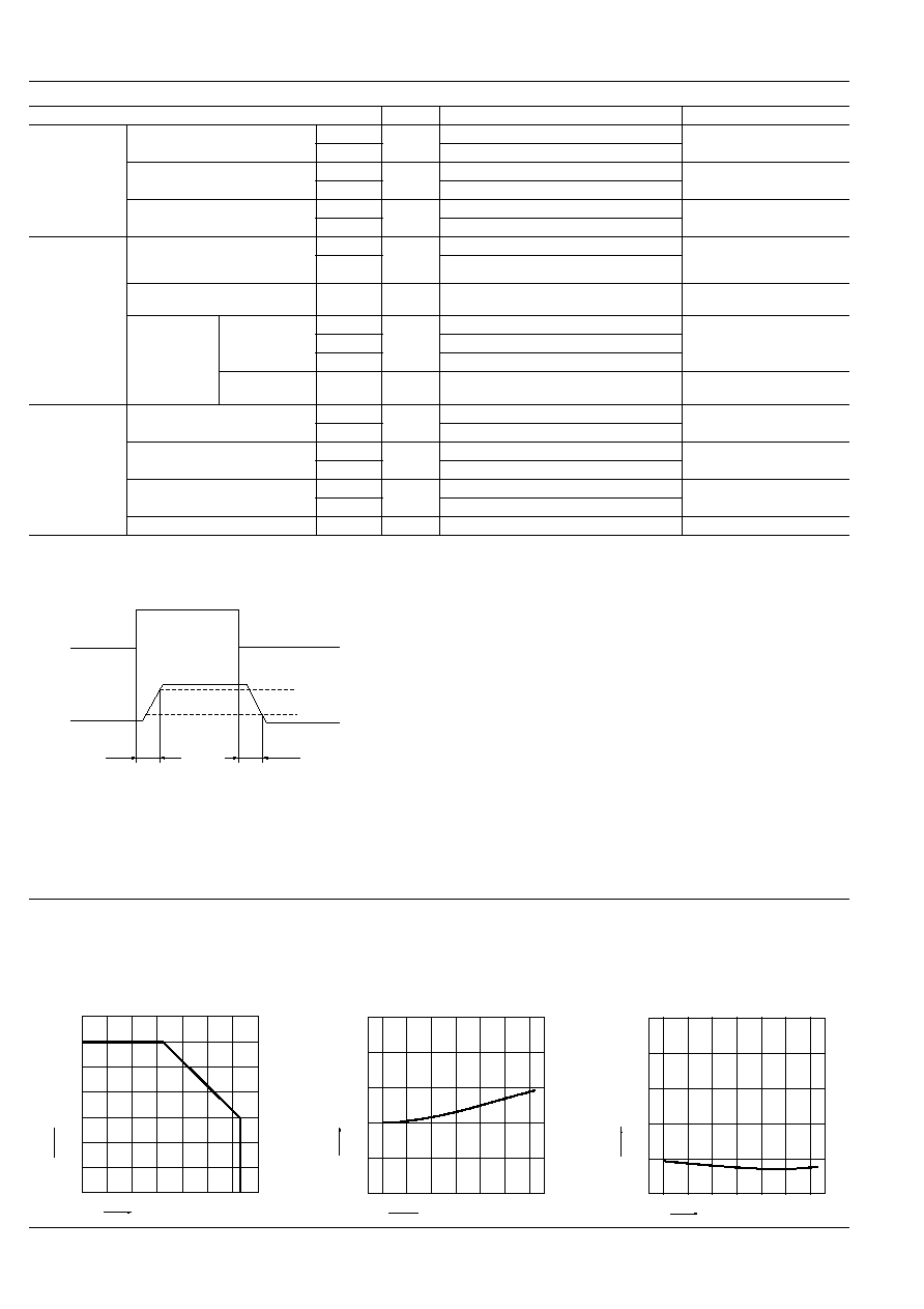
*Turn on/Turn off time
Item
Symbol
AQY210KS
Condition
Input
LED operate current
Typical
I
Fon
1.1 mA
I
L
= 120 mA
Maximum
3.0 mA
LED turn off current
Minimum
I
Foff
0.3 mA
I
L
= 120 mA
Typical
1.0 mA
LED dropout voltage
Typical
V
F
1.13 V (1.32 V at I
F
= 50mA)
I
F
= 5 mA
Maximum
1.5 V
Output
On resistance
Typical
R
on
23.5
I
F
= 5 mA
I
L
= 120 mA
Within 1 s on time
Maximum
35
Off state leakage current
Maximum
I
Leak
1
Ķ
A
I
F
= 0 mA
V
L
= 350 V
Over current
protection
Cut off current
Minimum
I
shut
160 mA
I
F
= 5 mA
Within 20ms on time
Typical
200 mA
Maximum
240 mA
Detection time
Typical
T
shut
50
Ķ
s
I
F
= 5 mA
V
L
= 350V DC short circuit
Transfer
characteristics
Turn on time*
Typical
T
on
0.7 ms
I
F
= 5 mA
I
L
= 120 mA
Maximum
2 ms
Turn off time*
Typical
T
off
0.07 ms
I
F
= 5 mA
I
L
= 120 mA
Maximum
1 ms
I/O capacitance
Typical
C
iso
0.8 pF
f = 1 MHz
V
B
= 0
Maximum
1.5 pF
Initial I/O isolation resistance
Minimum
R
iso
1,000 M
500 V DC
Toff
Input
Output
Ton
90%
10%
REFERENCE DATA
1. Load current vs. ambient temperature char-
acteristics
Allowable ambient temperature: ≠40
į
C to +85
į
C
≠40
į
F to +185
į
F
2. On resistance vs. ambient temperature char-
acteristics
Measured portion: between terminals 3 and 4;
LED current: 5 mA; Load voltage: Max. (DC)
Load current: Max.(DC)
3. Turn on time vs. ambient temperature char-
acteristics
Measured portion: between terminals 3 and 4;
LED current: 5 mA; Load voltage: 10V (DC);
Continuous load current: Max.(DC)
0
60
80
140
0
20
40
60
8085 100
≠40 ≠20
40
20
100
120
Ambient temperature,
į
C
Load current, mA
0
10
20
30
40
50
0
20
40
60
8085
≠40 ≠20
Ambient temperature,
į
C
On resistance,
0
2
3
≠40
≠20
5
0
20
40
60
80
1
4
85
Ambient temperature,
į
C
Turn on time, ms

AQY210KS
99
4. Turn off time vs. ambient temperature char-
acteristics
LED current: 5 mA; Load voltage: Max.(DC);
Continuous load current: Max.(DC)
5. LED operate current vs. ambient tempera-
ture characteristics
Load voltage: Max.(DC);
Continuous load current: Max.(DC)
6. LED turn off current vs. ambient temperature
characteristics
Load voltage: Max.(DC);
Continuous load current: Max.(DC)
Turn off time, ms
0
0.2
0.3
≠40
≠20
0.5
0
20
40
60
80 85
0.1
0.4
Ambient temperature,
į
C
0
1
2
3
≠40
≠20
5
0
20
40
60
80 85
4
LED operate current, mA
Ambient temperature,
į
C
LED turn off current, mA
Ambient temperature,
į
C
0
2
1
3
≠40
≠20
5
0
20
40
60
80 85
4
7. LED dropout voltage vs. ambient tempera-
ture characteristics
LED current: 5 to 50 mA
8. Voltage vs. current characteristics of output
at MOS portion
Measured portion: between terminals 3 and 4;
Ambient temperature: 25
į
C
77
į
F
9. Off state leakage current
Measured portion: between terminals 3 and 4;
Ambient temperature: 25
į
C
77
į
F
1.0
0
1.1
1.2
1.3
≠40 ≠20
0
20
40
60
80
1.4
1.5
85 100
LED dropout voltage, V
Ambient temperature,
į
C
50mA
30mA
20mA
10mA
5mA
≠200
200
150
100
50
0
≠50
≠100
≠150
2
0
4
6
≠2
≠4
≠6
Voltage,V
Current, mA
Off state leakage current, A
Load voltage, V
80
60
40
20
10
≠11
10
≠12
10
≠9
10
≠7
10
≠5
10
≠3
0
100
10. LED forward current vs. turn on time char-
acteristics
Measured portion: between terminals 3 and 4; Load
voltage: Max.(DC); Continuous load current:Max.(DC);
Ambient temperature: 25
į
C
77
į
F
11. LED forward current vs. turn off time char-
acteristics
Measured portion: between terminals 3 and 4; Load
voltage: Max.(DC); Continuous load current:Max.(DC);
Ambient temperature: 25
į
C
77
į
F
12. Applied voltage vs. output capacitance
characteristics
Measured portion: between terminals 3 and 4;
Frequency: 1 MHz; Ambient temperature: 25
į
C
77
į
F
Turn on time, ms
LED forward current, mA
0
0.5
1
10
0
20
30
40
1.5
50
Turn off time, ms
LED forward current, mA
0
0.05
0.15
0.1
10
0
20
30
40
0.2
50
Output capacitance, pF
Applied voltage, V
0
50
20
10
30
40
50
100
150
200
0
13. Cut off current vs. ambient temperature
characteristics
Measured portion: between terminals 3 and 4;
LED current: 5 mA, within 20ms on time
14. Detection time vs. ambient temperature
characteristics
Measured portion: between terminals 3 and 4;
LED current: 5 mA; Load voltage: Max.(DC);
Ambient temperature,
į
C
Cut off current, mA
0
100
50
150
200
≠40
≠20
300
0
20
40
60
80 85
250
Detection time,
Ķ
s
Ambient temperature,
į
C
0
100
50
150
200
≠40
≠20
300
0
20
40
60
80 85
250
AQY210KS
100
What is short circuit protection?
When the load current exceeds specifica-
tions, the short circuit protection function
kicks in and completely cuts off the load
current, thus turning off the relay.
The short circuit protection inside the
PhotoMOS relay instantaneously
(typ. 50 Ķs) and completely cuts of the
load current.
This protects any circuits that follow the
PhotoMOS relay from excess current.
There is almost no heating of the Photo-
MOS relay, which prevents it from becom-
ing damaged. To restore the function of
the relay turn off the input current and
then turn it back on.
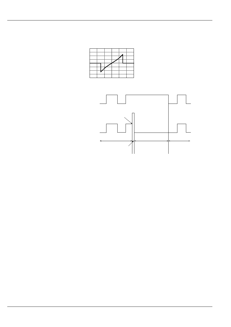
Output voltage and output current
characteristics
V-I characteristics of PhotoMOS relay
with short circuit protection circuit
Output voltage
Output current
Operation chart
Relay input
current
Relay output
current
5mA
120mA
0
0
Detection time
(approx. 50
Ķ
s)
Normal relay operation
Occurrence of
short circuit current
Abnormal current
The short circuit current
detection device latches
when the relay is off.
The relay operates normally
when the input current is reset.
If the output section shorts even after
the input current is reset, it will latch
when the short circuit current is
detected again and the relay turns off.
5/7/2001
All Rights Reserved, © Copyright Matsushita Electric Works, Ltd.