 | –≠–ª–µ–∫—Ç—Ä–æ–Ω–Ω—ã–π –∫–æ–º–ø–æ–Ω–µ–Ω—Ç: ASX200xx | –°–∫–∞—á–∞—Ç—å:  PDF PDF  ZIP ZIP |

SX
120
SX-RELAYS
HIGH SENSITIVITY RELAY
WITH GUARANTEED LOW
LEVEL SWITCHING
CAPACITY
7.4
.291
15.0
.591
8.2
.323
mm
inch
7.4
.291
15.0
.591
Max. 10.0
.394
FEATURES
1. High contact reliability over a long
life has been made possible for low
level loads.
Using a low level load (1 mV 10
µ
A to 10 V
10 mA) 10
7
operations were achieved with
a static contact resistance of Max. 100
m
(voltage drop of 20 mV, 1 mA, 1 kHz)
and a dynamic contact resistance of Max.
1
(Measurement delay 10 ms, voltage
drop of 20 mV, 1 mA, 1 kHz).
2. High sensitibity of 50 mW
By using the highly efficient polar magnet-
ic circuit "seesaw balance armature
mechanism", a rated power consumption
of 50 mW (for single side stable type) has
been achieved.
3. Low thermal electromotive force
Reducing the heat from the coil enables a
thermal electromotive force of 3
µ
V or
less.
SPECIFICATIONS
Contact
Notes:
**
1
This value can change due to the switching frequency, environmental conditions,
and desired reliability level, therefore it is recommended to check this with the ac-
tual load.
**
2
For single side stable only.
Characteristics
Remarks:
* Specifications will vary with foreign standards certification ratings.
*
1
By nominal switching capacity: No. of operations: 10
7
*
2
Measurement at same location as "Initial breakdown voltage" section.
*
3
Detection current: 10mA.
*
4
Nominal voltage applied to the coil, excluding contact bounce time.
*
5
By resistive method, nominal voltage applied to the coil; contact carrying current:
10mA.
*
6
Half-wave pulse of sine wave: 6 ms; detection time: 10
µ
s.
*
7
Half-wave pulse of sine wave: 6 ms.
*
8
Detection time: 10
µ
s.
*
9
Refer to 5. Conditions for operation, transport and storage mentioned in
AMBIENT ENVIRONMENT (Page 61)
Arrangement
2 Form C
Static contact resistance (During initial and
electric life tests)*
1
(By voltage drop of 20 mV 1 mA [1kHz])
Max. 100 m
Dynamic contact resistance (During initial and
electric life tests)*
1
(By voltage drop of 20 mV 1 mA[1 kHz], Mea-
surement delay 10 ms after applying nominal
coil voltage)
Max. 1
Contact material
Gold-clad silver alloy
Rating
Nominal switching capacity
(resistive load)
10 mA 10 VDC
Max. switching power
0.1 W
Max. switching voltage
10 VDC
Max. switching current
10 mA DC
Min. switching capacity**
1
10
µ
A 1 mVDC
Nominal
operating
power
Single side stable
50mW (1.5 to 12 V DC)
70mW (24 V DC)
1 coil latching
35mW (1.5 to 12 V DC)
50mW (24 V DC)
2 coil latching
70mW (1.5 to 12 V DC)
150mW (24 V DC)
Thermal electromotive force, max.
(at nominal voltage applied to the coil**
2
)
3
µ
V
Expected
life (min.
operations)
Mechanical (at 750 cpm)
5
◊
10
7
Electrical (at 750 cpm)
(10 mA 10 V DC resistive load)
10
7
Initial insulation resistance*
2
Min. 10,000M
(at 500V DC)
Initial
breakdown
voltage*
3
Between open contacts
750 Vrms for 1min.
Between contact sets
1,000 Vrms for 1min.
Between contact and coil
1,800 Vrms for 1min.
Operate time [Set time]*
4
(at 20
∞
C)
Max. 5 ms (Approx. 3 ms)
[Max. 5 ms (Approx. 3 ms)]
Release time (without diode)
[Reset time]*
4
(at 20
∞
C)
Max. 5 ms (Approx. 1.5 ms)
[Max. 5 ms (Approx. 3 ms)]
Temperature rise*
5
(at 20
∞
C)
Max. 50
∞
C
Shock resistance
Functional*
6
Min. 750 m/s
2
{75G]
Destructive*
7
Min. 1,000 m/s
2
{100G]
Vibration resistance
Functional*
8
10 to 55 Hz at double
amplitude of 3.3 mm
Destructive
10 to 55 Hz at double
amplitude of 5 mm
Conditions for operation,
transport and storage*
9
(Not freezing and con-
densing at low tempera-
ture)
Ambient
temperature
≠40
∞
C to 70
∞
C
≠40
∞
F to 158
∞
F
Humidity
5 to 85% R.H.
Unit weight
Approx. 2 g
.071 oz
TYPICAL APPLICATIONS
This relay will be used for the small load
for measuring instruments or others
where a stable contact resistance is
required.
TESTING

SX
121
ORDERING INFORMATION
2
0
0
A
Z
1
H
Ex. ASX
Contact arrangement
Terminal shape
Operating function
Packing style
Coil voltage (DC)
Nil: Standard PC board terminal
A: Surface-mount terminal
2: 2 Form C
0: Single side stable
1: 1 coil latching
2: 2 coil latching
Type of operation
0: Standard type
(B.B.M.)
Nil: Tube packing
Z: Tape and reel packing
(piked from 8/9/10/12
pin side)
1H: 1.5V
03 : 3V
4H: 4.5V
06 : 6V
09 : 9V
12 : 12V
24 : 24V
Note: Tape and reel packing symbol "-Z" is not marked on the relay. "X" type tape and reel packing (picked from 1/3/4/5-pin side) is also available. Suffix "X" instead of "Z".
TYPES AND COIL DATA (at 20
∞
C
68
∞
F
)
(1) Standard PC board terminal
1) Standard packing: 40 pcs. in an inner package (tube); 1,000 pcs. in an outer package
2) Specified value of pick-up, drop-out, set and reset voltage is with the condition of square wave coil pulse.
Single side stable
1 coil latching
2 coil latching
Part No.
Coil Rating,
V DC
Pick-up voltage,
V DC (max.)
(initial)
Drop-out
voltage,
V DC (min.)
(initial)
Nominal
operating current,
mA (
±
10%)
Coil resistance,
(
±
10%)
Nominal
operating power,
mW
Max. allowable
voltage,
V DC
Standard PC
board terminal
ASX2001H
1.5
1.2
0.15
33.3
45
50
2.25
ASX20003
3
2.4
0.3
16.7
180
50
4.5
ASX2004H
4.5
3.6
0.45
11.1
405
50
6.75
ASX20006
6
4.8
0.6
8.3
720
50
9
ASX20009
9
7.2
0.9
5.6
1,620
50
13.5
ASX20012
12
9.6
1.2
4.2
2,880
50
18
ASX20024
24
19.2
2.4
2.9
8,229
70
36
Part No.
Coil Rating,
V DC
Set voltage,
V DC (max.)
(initial)
Reset voltage,
V DC (max.)
(initial)
Nominal
operating current,
mA (
±
10%)
Coil resistance,
(
±
10%)
Nominal
operating power,
mW
Max. allowable
voltage,
V DC
Standard PC
board terminal
ASX2101H
1.5
1.2
1.2
23.3
64.3
35
2.25
ASX21003
3
2.4
2.4
11.7
257
35
4.5
ASX2104H
4.5
3.6
3.6
7.8
579
35
6.75
ASX21006
6
4.8
4.8
5.8
1,029
35
9
ASX21009
9
7.2
7.2
3.9
2,314
35
13.5
ASX21012
12
9.6
9.6
2.9
4,114
35
18
ASX21024
24
19.2
19.2
2.1
11,520
50
36
Part No.
Coil Rating,
V DC
Set voltage,
V DC (max.)
(initial)
Reset voltage,
V DC (max.)
(initial)
Nominal
operating current,
mA (
±
10%)
Coil resistance,
(
±
10%)
Nominal
operating power,
mW
Max. allowable
voltage, V DC
Standard PC
board terminal
Set coil
Reset
coil
Set coil
Reset
coil
Set coil
Reset
coil
ASX2201H
1.5
1.2
1.2
46.7
46.7
32.1
32.1
70
70
2.25
ASX22003
3
2.4
2.4
23.3
23.3
129
129
70
70
4.5
ASX2204H
4.5
3.6
3.6
15.6
15.6
289
289
70
70
6.75
ASX22006
6
4.8
4.8
11.7
11.7
514
514
70
70
9
ASX22009
9
7.2
7.2
7.8
7.8
1,157
1,157
70
70
13.5
ASX22012
12
9.6
9.6
5.8
5.8
2,057
2,057
70
70
18
ASX22024
24
19.2
19.2
6.3
6.3
3,840
3,840
150
150
36

SX
122
(2) Surface-mount terminal
1) Standard packing: 40 pcs.(tube), 1,000pcs. (tape and reel)in an inner package; 500 pcs.(tube), 1,000pcs. (tape and reel)in an outer
package
2) Specified value of pick-up, drop-out, set and reset voltage is with the condition of square wave coil pulse.
Single side stable
1 coil latching type
2 coil latching type
Part No.
Coil Rating,
V DC
Pick-up
voltage,
V DC (max.)
(initial)
Drop-out
voltage,
V DC (min.)
(initial)
Nominal
operating
current,
mA (
±
10%)
Coil resistance,
(
±
10%)
Nominal
operating
power,
mW
Max.
allowable
voltage,
V DC
Tube packing
Tape and reel
packing
ASX200A1H
ASX200A1HZ
1.5
1.2
0.15
33.3
45
50
2.25
ASX200A03
ASX200A03Z
3
2.4
0.3
16.7
180
50
4.5
ASX200A4H
ASX200A4HZ
4.5
3.6
0.45
11.1
405
50
6.75
ASX200A06
ASX200A06Z
6
4.8
0.6
8.3
720
50
9
ASX200A09
ASX200A09Z
9
7.2
0.9
5.6
1,620
50
13.5
ASX200A12
ASX200A12Z
12
9.6
1.2
4.2
2,880
50
18
ASX200A24
ASX200A24Z
24
19.2
2.4
2.9
8,229
70
36
Part No.
Coil Rating,
V DC
Set voltage,
V DC (max.)
(initial)
Reset
voltage,
V DC (max.)
(initial)
Nominal
operating
current,
mA (
±
10%)
Coil resistance,
(
±
10%)
Nominal
operating
power,
mW
Max.
allowable
voltage,
V DC
Tube packing
Tape and reel
packing
ASX210A1H
ASX210A1HZ
1.5
1.2
1.2
23.3
64.3
35
2.25
ASX210A03
ASX210A03Z
3
2.4
2.4
11.7
257
35
4.5
ASX210A4H
ASX210A4HZ
4.5
3.6
3.6
7.8
579
35
6.75
ASX210A06
ASX210A06Z
6
4.8
4.8
5.8
1,029
35
9
ASX210A09
ASX210A09Z
9
7.2
7.2
3.9
2,314
35
13.5
ASX210A12
ASX210A12Z
12
9.6
9.6
2.9
4,114
35
18
ASX210A24
ASX210A24Z
24
19.2
19.2
2.1
11,520
50
36
Part No.
Coil Rating,
V DC
Set voltage,
V DC (max.)
(initial)
Reset
voltage,
V DC (max.)
(initial)
Nominal
operating
current,
mA (
±
10%)
Coil resistance,
(
±
10%)
Nominal
operating
power,
mW
Max.
allowable
voltage,
V DC
Tube packing
Tape and reel
packing
Set
coil
Reset
coil
Set
coil
Reset
coil
Set
coil
Reset
coil
ASX220A1H
ASX220A1HZ
1.5
1.2
1.2
46.7
46.7
32.1
32.1
70
70
2.25
ASX220A03
ASX220A03Z
3
2.4
2.4
23.3
23.3
129
129
70
70
4.5
ASX220A4H
ASX220A4HZ
4.5
3.6
3.6
15.6
15.6
289
289
70
70
6.75
ASX220A06
ASX220A06Z
6
4.8
4.8
11.7
11.7
514
514
70
70
9
ASX220A09
ASX220A09Z
9
7.2
7.2
7.8
7.8
1,157
1,157
70
70
13.5
ASX220A12
ASX220A12Z
12
9.6
9.6
5.8
5.8
2,057
2,057
70
70
18
ASX220A24
ASX220A24Z
24
19.2
19.2
6.3
6.3
3,840
3,840
150
150
36
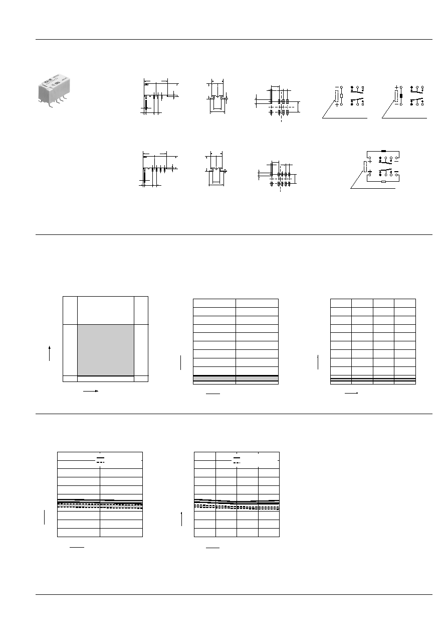
DIMENSIONS
1. PC board terminal
Single side stable/
1 coil latching
0.5
.020
1.15
.045
2.54
.100
3.5
.138
0.65
.026
5.08
.200
0.25
.010
15.0
.591
5.08
.200
8.2
.323
7.4
.291
mm
inch
2 coil latching
0.5
.020
1.15
.045
2.54
.100
3.5
.138
0.65
.026
5.08
.200
0.25
.010
15.0
.591
5.08
.200
8.2
.323
7.4
.291
General tolerance:
±
0.3
±
.012
PC board pattern
5.08
.200
2.54
.100
8-1.0 dia.
8-.039 dia.
10.16
.400
5.08
.200
2.54
.100
10-1.0 dia.
10-.039 dia.
12.7
.500
Tolerance:
±
0.1
±
.004
Schematic (Bottom view)
Single side stable
(Deenergized condition)
1 coil latching
(Reset condition)
Direction indication
12 10 9 8
1
3 4 5
Direction indication
12 10 9 8
1
3 4 5
2 coil latching
(Reset condition)
Direction indication
12 10 9 8 7
1
3
4 5 6
SX
123
2. Surface-mount terminal
Single side stable/
1 coil latching
5.08
.200
5.08
.200
2.54
.100
0.65
.026
9.4
±
0.5
.370
±
.020
15.0
.591
0.5
.020
8.2
.323
7.4
.291
Max.10.0
.394
0.25
.010
1.15
.045
mm
inch
2 coil latching
5.08
.200
5.08
.200
2.54
.100
0.65
.026
0.25
.010
9.4
±
0.5
.370
±
.020
0.5
.020
8.2
.323
15.0
.591
Max.10.0
.394
7.4
.291
1.15
.045
General tolerance:
±
0.3
±
.012
Suggested
mounting pad
5.08
.200
,
,,
,,
,,,,
,,
,,
,,
,
,,
,
,
,,
,,,
,,,
,,
,
,,
,
,,
,,
,
,,
,,
,
,,
,,
,
,,
,
,,
,,
,,
,,
,,
,
,,
,
,,
,,
,,
,,
,,
,,
,
,
,,
,
,
,
,
,,
,
,
,,
,,
,
1.0
.039
2.54
.100
3.16
.124
7.24
.285
5.08
.200
1.0
.039
2.54
.100
3.16
.124
7.24
.285
,,
,,
,,,,
,,
,
,
,
,
,
,,
,
,
,
,
,,
,,
,,
,,
,,
,,
,,
,
,
,,
,
,,
,,
,
,
,,
,
,,
,,
,,
,,
,,
,
,,
,,
,
,,
,
,,
,,
,,
,
,
,
,,
,
,
,
,
,
,,
,
,
,
,
,
,,
,,
Tolerance:
±
0.1
±
.004
Schematic (Top view)
Single side stable
(Deenergized condition)
1 coil latching
(Reset condition)
Direction indication
12 10 9 8
1
3 4 5
Direction indication
12 10 9 8
1
3 4 5
2 coil latching
(Reset condition)
Direction indication
12 10 9 8 7
1
3
4 5 6
REFERENCE DATA
1. Switching capacity range
2-(1). Change in dynamic contact resistance
(10 mA 10 V DC resistive load)
Tested: ASX20012, Quantity: n=10
Operating frequency: 750 cpm
Measured condition: 10 ms after applying nominal coil
voltage, using voltage drop of 20 mV, 1 mA, 1 kHz.
2-(2). Change in dynamic contact resistance
(10
µ
A 1 mV DC resistive load)
Tested: ASX20012, Quantity: n=10
Operating frequency: 750 cpm
Measured condition: 10 ms after applying nominal coil
voltage, using voltage drop of 20 mV, 1 mA, 1 kHz.
10mA
10
µ
A
1mV
10V
Contact voltage
Contact current
1,000
0
Min.
0
0.1
0.2
0.3
0.4
0.5
0.6
0.7
0.8
0.9
1.0
Max.
No. of operations,
◊
10
4
Contact resistance,
2,000
1,000
0
Min.
0
0.1
0.2
0.3
0.4
0.5
0.6
0.7
0.8
0.9
1.0
Max.
No. of operations,
◊
10
4
Contact resistance,
3-(1). Change in static contact resistance
(10 mA 10 V DC resistive load)
Tested: ASX20012, Quantity: n=10
Operating frequency: 750 cpm
3-(2). Change in static contact resistance
(10
µ
A 1 mVDC resistive load)
Tested: ASX20012, Quantity: n=10
Operating frequency: 750 cpm
1,000
0
10
20
30
40
50
60
70
80
90
0
Max.
Min.
Max.
Min.
0
10
20
30
40
50
60
80
90
100
No. of operations,
◊
10
4
Contact resistance, m
N.C. side contact
N.O. side contact
2,000
1,000
0
10
20
30
40
50
60
70
80
90
0
Max.
Min.
Max.
Min.
0
10
20
30
40
50
60
80
90
100
No. of operations,
◊
10
4
Contact resistance, m
N.C. side contact
N.O. side contact
SX
124
NOTES
1. Coil operating power
1) As a general rule, only a pure DC pow-
er supply should be used for the coil drive.
2) To ensure proper operation, the voltage
applied to both terminals of the coil should
be
±
5% (at 20
∞
C
68
∞
F
) the rated operating
voltage of the coil. Also, be aware that the
pick-up and drop-out voltages will fluctu-
ate depending on the ambient tempera-
ture and operating conditions.
3) The ripple factor for the voltage applied
to the coil should be less than 5%.
4) For set and reset latching relays, the
rated operating voltage should be applied
to the coil for 10 ms or more.
2. Coil connection
When connecting coils, refer to the wiring
diagram to prevent mis-operation or mal-
function.
3. External magnetic field
Since SX relays are highly sensitive polar-
ized relays, their characteristics will be af-
fected by a strong external magnetic field.
Avoid using the relay under that condition.
4. Cleaning
In automatic cleaning, cleaning with the
boiling method is recommended. Avoid ul-
trasonic cleaning which subject the relay
to high frequency vibrations. It may cause
the contacts to stick.
lt is recommended that a fluorinated hy-
drocarbon or other alcoholic solvent be
used.
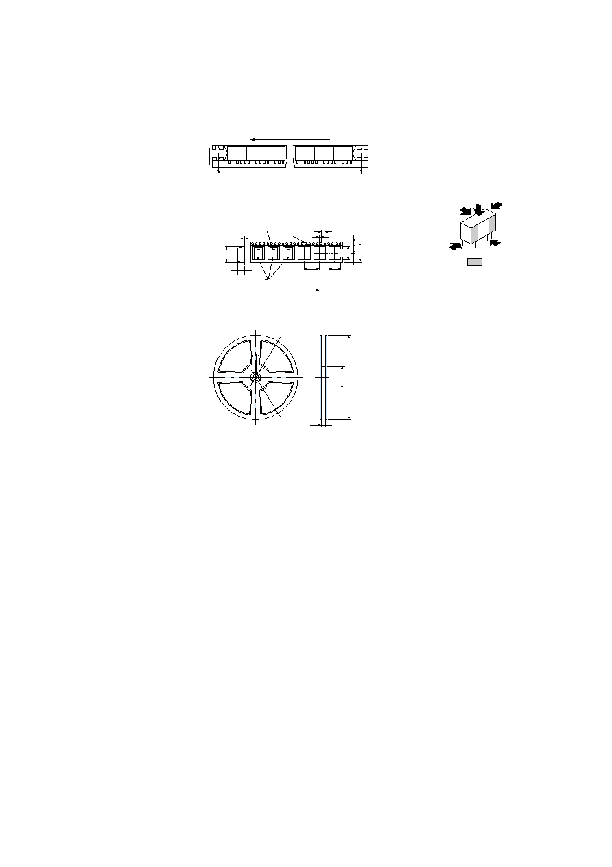
5. Packing style
1) The relay is packed in a tube with the
relay orientation mark on the left side, as
shown in the figure below.
2) Tape and reel packing
(1) Tape dimensions
mm
inch
(2) Dimensions of plastic reel
mm
inch
6. Automatic insertion
To maintain the internal function of the re-
lay, the chucking pressure should not ex-
ceed the values below.
Chucking pressure in the direction A:
4.9 N {500 gf} or less
Chucking pressure in the direction B:
9.8 N {1 kgf} or less
Chucking pressure in the direction C:
9.8 N {1 kgf} or less
Please chuck the
portion.
Avoid chucking the center of the relay.
In addition, excessive chucking pressure
to the pinpoint of the relay should be also
avoided.
Orientation (indicates PIN No.1)stripe
Stopper (gray)
Stopper (green)
SX relays
Relay polarity bar
(Z type)
Tape coming out direction
General tolerance
±
0.1 mm
.004 inch
4.0
±
0.1
.157
±
.004
1.75
±
0.1
.069
±
.004
2.0
±
0.1
.079
±
.004
0.40
±
0.1
.016
±
.004
10.8
±
0.2
.425
±
.008
16.0
±
0.1
.630
±
.004
10.0
±
0.1
.394
±
.004
1.50 dia.
.059 dia.
+0.1
0
+.003
.0
,
11.5
±
0.1
.453
±
.004
15.5
±
0.1
.610
±
.004
Max. 20.0
.787
24.0
±
0.3
.945
±
.012
21
±
0.8 dia.
.827
±
.031 dia.
13
±
0.2 dia.
.512
±
.008 dia.
24.4
.961
+2
0
+.079
0
100
±
1 dia.
3.937
±
.039 dia.
2.0
±
0.2
.079
±
.008
370
±
2 dia.
14.567
±
.079 dia.
2.0
±
0.5
.079
±
.020
A
C
B
For Cautions for Use, see Relay Technical Information (Page 48 to 76).
9/1/2000
All Rights Reserved, © Copyright Matsushita Electric Works, Ltd.
Go To Online Catalog