Document Outline
- ˛ˇ
- ˛ˇ
- ˛ˇ
- ˛ˇ
- ˛ˇ
- ˛ˇ
- ˛ˇ
- ˛ˇ
- ˛ˇ
- ˛ˇ
- ˛ˇ
- ˛ˇ
- ˛ˇ
- ˛ˇ
- ˛ˇ
- ˛ˇ
- ˛ˇ
- ˛ˇ
DESCRIPTION
NL6448AC20-06 is a TFT(thin film transistor) active matrix color liquid crystal display(LCD) comprising amor-
phous silicon TFT attached to each signal electrode, a driving circuit and a backlight. NL6448AC20-06 has a built-
in backlight. Backlight includes long-life-lamps and its lamps are replaceable.
The 17cm diagonal display area contains 640
◊
480 pixels and can display 4096 or 262144 colors simultane-
ously.
NL6448AC20-06 is suitable for industrial application use, because the luminance is high, and the viewing
direction is selectable by display scan select.
FEATURES
TM High luminance (200 cd/m
2
Typ.: saturated value)
TM Low reflection
TM Wide viewing angle with retardation film
TM Display reverse scan function
TM 6-bit/4-bit digital RGB signals
TM Edge type backlight with long-life-lamps (Two lamp holders, inverter)
TM Variable luminance control
TM Backlight lamp holder (65LHS-3L) replaceable
TM Compatible to the mounting hole position of NL6448AC20-02 except for inverter.
APPLICATIONS
TM Measuring instruments
TM Display terminals for control system
TM New media
TM Control boards for NC machine
TM Monitor for process controller
DATA S H E E T
NL6448AC20-06
TFT COLOR LCD MODULE
1997
©
17 cm (6.5 type), 640
◊
480 pixels
262144/4096 colors, incorporated edge-light type backlight
high brightness, inverter separated from module
Document No. EN0323EJ1V0DS00 (1st edition)
Date Published July 1997 M
Printed in Japan
NL6448AC20-06
2
STRUCTURE AND FUNCTIONS
A TFT color LCD module comprises a TFT LCD panel, LSIs for driving liquid crystal, and a backlight. The TFT
LCD panel is composed of a TFT array glass substrate superimposed on a color filter glass substrate with liquid
crystal filled in the narrow gap between two substrates. The backlight apparatus is located on the backside of the
LCD panel.
RGB (Red, Green, Blue) data signals are sent to LCD panel drivers after modulation into suitable forms for
active matrix addressing through signal processor.
Each of the liquid crystal cells acts as an electro-optical switch that controls the light transmission from the
backlight by a signal applied to a signal electrode through the TFT switch.
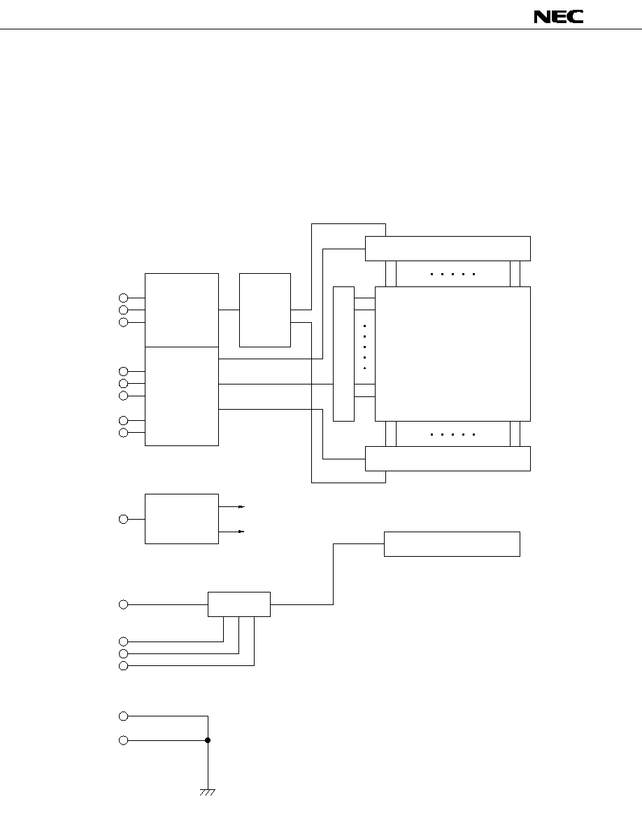
BLOCK DIAGRAM
R0 ≠ R5
G0 ≠ G5
B0 ≠ B5
CLK
Hsync
Vsync
BRTL
BRTH
GNDB
DE
DPS
VCC
LSIs
Drivers
Inverter
Power
supply
circuit
LCD timing
controller
Digital signal
processor
Level shift
H ≠ driver
Backlight
H ≠ driver
960 lines
960 lines
480 lines
V ≠ driver
TFT LCD panel
H : 640
◊
3 (RGB)
V : 480
VDD
GND(SG)
Frame(FG)

3
NL6448AC20-06
OUTLINE OF CHARACTERISTICS (at room temperature)
Display area
132.48 (H)
◊
99.36 (V) mm
Drive system
a-Si TFT active matrix
Display colors
262144 or 4096 colors
Number of pixels
640
◊
480
Pixel arrangement
RGB vertical stripe
Pixel pitch
0.207 (H)
◊
0.207 (V) mm
Module size
178.8(H)
◊
126.8(V)
◊
11.0 Typ. (D) mm
Inverter size
26 (H)
◊
105 (V)
◊
9.5 Typ. (D) mm
Weight
237g (Typ.) + 17g (Typ., inverter)
Contrast ratio
150 : 1 (Typ.)
Viewing angle (more than the contrast ratio of 10:1)
∑ Horizontal : 50
∞
(Typ. left side, right side)
∑ Vertical : 35
∞
(Typ. up side), 45
∞
(Typ. down side)
Designed viewing direction
∑ wider viewing angle with contrast ratio
: up side (12 o'clock, reverse scan)
: down side (6 o'clock, normal scan)
∑ wider viewing angle without image reversal : up side (12 o'clock, normal scan)
: down side (6 o'clock, reverse scan)
∑ optimum grayscale (
= 2.2)
: perpendicular
Color gamut
45% (Typ. At center, To NTSC)
Response time
40ms (Max.), "white" to "black"
Luminance
200cd/m
2
(Typ.)
Signal system
6-/4-bit digital signals for each of RGB primary colors,
Synchronous signals (Hsync, Vsync), Dot clock (CLK)
Supply voltage
5.0V (Logic, LCD driving), 5.0V (Backlight)
Backlight
Edge light type: two fluorescent lamps (cold cathode type)
Power consumption
6.0W (Typ.)
5
NL6448AC20-06
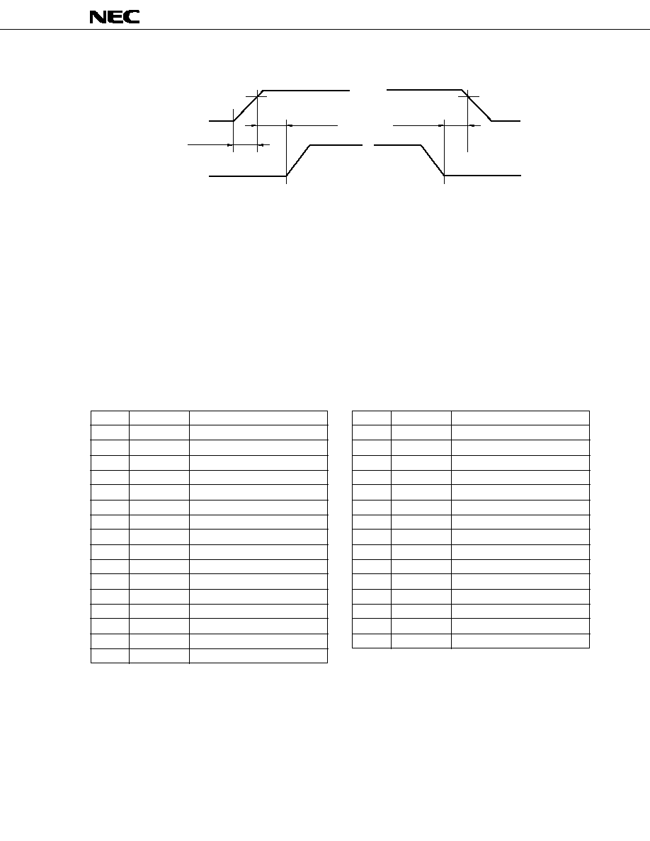
SUPPLY VOLTAGE SEQUENCE
4.75 V
VCC
Signal
4.75 V
0 V
t<150 ms
0<t<35 ms
0<t<35 ms
0 V
Power-on
VALID
Power-off
1 The supply voltage for input signals should be the same as VCC.
2 Apply VDD within the LCD operation period. When the backlight turns on before LCD operation or the LCD operation turns
off before the backlight turns off, the display may momentarily become white.
3 When the power is off, please keep whole signals (Hsync, Vsync, CLK, DE, and DATA) low level or high impedance.
INTERFACE PIN CONNECTION
Module side connector
Mating connector
CN31 ∑ ∑ ∑ IL-310-T31PB-VF (No. 1 to 31)
IL-310-T31S-VF
Supplier : Japan Aviation Electronics
or
Industry Limited (JAE)
DF9-31S-1V or DF9M-31S-1R
Supplier : HIROSE ELECTRIC CO., LTD
(1) 6-bit interface signals, power supply
Pin No.
Symbol
Function
1
GND
Ground
2
CLK
Dot clock
3
Hsync
Horizontal synchronous
4
Vsync
Vertical synchronous
5
GND
Ground
6
R0
Red data (LSB)
7
R1
Red data
8
R2
Red data
9
R3
Red data
10
R4
Red data
11
R5
Red data (MSB)
12
GND
Ground
13
G0
Green data (LSB)
14
G1
Green data
15
G2
Green data
16
G3
Green data
Pin No.
Symbol
Function
17
G4
Green data
18
G5
Green data (MSB)
19
GND
Ground
20
B0
Blue data (LSB)
21
B1
Blue data
22
B2
Blue data
23
B3
Blue data
24
B4
Blue data
25
B5
Blue data (MSB)
26
GND
Ground
27
DE
Data enable
28
V
CC
Power supply
29
V
CC
Power supply
30
N.C.
Non-connection (Open)
31
DPS
Display scan select
LSB : Least Significent Bit
MSB : Most Significent Bit
note 1 : VCC : All VCC terminals should be connected to 5.0 V.
note 2 : DPS : Normal scan is "L"or "Open". And reverse scan is "H".
note 3 : During the operation, do not change the operation mode : e. g. scan direction and 4/6-bit signal.
note 4 : Do not operate LCD module without input DE signal.