
Fea tures
∑
Industrial package
∑
Threaded housing
∑
Molded connectors
De scrip tion
The OPB856 consists of an LED and
a phototransistor each mounted in a
threaded (M12x1TH) color coded
housing. The LED is white, and the
phototransistor is black. Both have a
molded Molex connector for ease of
installation. For cable and connector
operations, contact the factory.
Ab so lute Maxi mum Rat ings (T
A
= 25
o
C un less oth er wise noted)
Stor age and Op er at ing Tem pera ture Range . . . . . . . . . . . . . . . . . . . -40
o
C to +85
o
C
In put Di ode
Con tinu ous For ward Cur rent . . . . . . . . . . . . . . . . . . . . . . . . . . . . . . . . . . . . . . . 40 mA
Re verse Volt age. . . . . . . . . . . . . . . . . . . . . . . . . . . . . . . . . . . . . . . . . . . . . . . . . . 2.0 V
Power Dis si pa tion . . . . . . . . . . . . . . . . . . . . . . . . . . . . . . . . . . . . . . . . . . . . 100 mW
(1)
Out put Pho to tran sis tor
Collector- Emitter Volt age. . . . . . . . . . . . . . . . . . . . . . . . . . . . . . . . . . . . . . . . . . . . 30 V
Emitter- Collector Volt age. . . . . . . . . . . . . . . . . . . . . . . . . . . . . . . . . . . . . . . . . . . . 5.0 V
Power Dis si pa tion . . . . . . . . . . . . . . . . . . . . . . . . . . . . . . . . . . . . . . . . . . . . 100 mW
(1)
Notes:
(1) Derate Linearly 1.67 mW/
o
C above 25
o
C.
(2) d is the distance between lenses along the optical axis.
(3) All parameters tested using pulse technique.
Prod uct Bul le tin OPB856
July 1996
Wide Gap Op ti cal Sen sor
Type OPB856
Op tek Tech nol ogy, Inc. 1215 W. Crosby Road Car roll ton, Texas 75006 (972) 323- 2200 Fax (972) 323- 2396
12-130
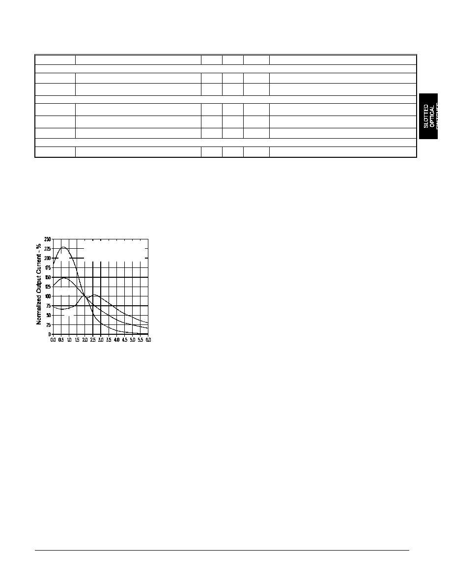
Type OPB856
Normalized Output Current vs.
Distance
d - Distance Between LED and
Sensor Housings - Inches
Normalized to d = 2.0"
I
F
= 20 mA
V
CE
= 5.0 V
+2
Average
-2
Elec tri cal Char ac ter is tics (T
A
= 25
o
C un less oth er wise noted)
SYM BOL
PA RAME TER
MIN MAX UNITS
TEST CON DI TIONS
In put Di ode
V
F
Forward Voltage
1.7
V
I
F
= 20 mA
I
R
Reverse Current
100
µ
A
V
R
= 2 V
Out put Pho to tran sis tor
V
(BR)CEO
Collector-Emitter Breakdown Voltage
30
V
I
C
= 100
µ
A
V
(BR)ECO
Emitter-Collector Breakdown Voltage
5.0
V
I
E
= 100
µ
A
I
CEO
Collector Dark Current
100
nA
V
CE
= 10 V, I
F
= 0, E
e
= 0
Cou pled
I
C(ON)
On-State Collector Current
(3)
1.8
mA
V
CE
= 5 V, I
F
= 20 mA, d = 2"
(2)
Typi cal Per form ance Curves
12-131
Optek reserves the right to make changes at any time in order to improve design and to supply the best product possible.
Op tek Tech nol ogy, Inc. 1215 W. Crosby Road Car roll ton, Texas 75006 (972) 323- 2200 Fax (972) 323- 2396