 | –≠–ª–µ–∫—Ç—Ä–æ–Ω–Ω—ã–π –∫–æ–º–ø–æ–Ω–µ–Ω—Ç: AN7280S | –°–∫–∞—á–∞—Ç—å:  PDF PDF  ZIP ZIP |
ICs for FM/AM Tuner
s
Overview
The AN7280S is an FM front-end IC designed for DTS
except RF amp. of car radio. It features built-in local oscil-
lation frequency buffer output, PIN diode driver for anten-
na damping and SSC (search stop control).
s
Features
∑
High sensitivity, high S/N ratio
∑
Good IM characteristics at strong input
∑
Available for two loop AGC (keyed AGC)
∑
Pre IF amp. gain variable
∑
PIN diode driver (ADX) built-in
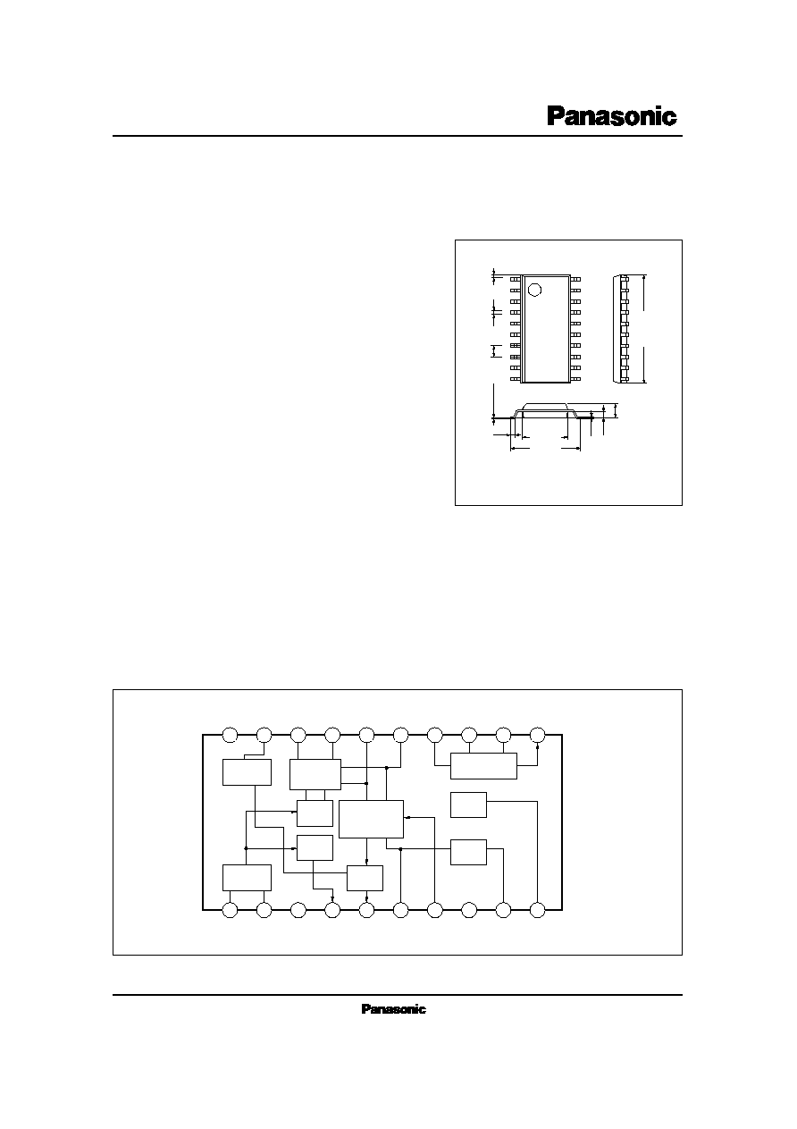
AN7280S
FM Front-end IC for Car Radio
Unit : mm
0.1
±
0.1
1.5
±
0.2
0.3
0.65
0.15
0.4
1
2
3
4
5
6
7
8
9
10
20
19
18
17
16
15
14
13
12
11
0.4
±
0.25
1.27
12.6
±
0.3
5.4
±
0.3
7.7
±
0.3
20
19
18
17
16
15
14
13
12
11
1
2
3
4
5
6
7
8
9
10
ADX
Mixer
Buffer
Buffer
OSC
Det.
AGC Amp.
IF Amp.
V
REG
SSC
GND
GND
V
CC
s
Block Diagram
20-Lead SOP Package (SOP020-P-0300B)

AN7280S
ICs for FM/AM Tuner
V
CC
I
CC
P
D
T
opr
T
stg
Supply Voltage
Supply Current
Power Dissipation
Operating Ambient Temperature
Storage Temperature
V
mA
mW
∞C
∞C
Parameter
Symbol
Rating
Unit
s
Absolute Maximum Ratings
(Ta=25∞C)
9.2
50
460
≠40 ~ + 85
≠55 ~ + 150
s
Recommended Operating Range
(Ta=25∞C)
Parameter
Symbol
Range
Operating Supply Voltage Range
V
CC
6.8V ~ 9.2V
Parameter
Symbol
Condition
min.
typ.
max.
Unit
s
Electrical Characteristics
(Ta=25∞C)
S/N Ratio
Local Oscillation Level
IF Output Level
AGC Level (L)
AGC Level (H)
N
OUT
V
OSC
V
OUT
V
AGC (L)
V
AGC (H)
V
CC
= 8V, V
in
=17dB
µ
No modulation
However, S= output at 400Hz, 30%modulation
V
CC
= 8V, f
OSC
= 108.7MHz
Measured by Pin4, No signal input
V
CC
= 8V, V
in
= 51dB
µ
V
CC
= 8V, V
in
= 67dB
µ
V
CC
= 8V, V
in
= 53dB
µ
22
219
41
6
30
384
58
0.05
6.5
435
82
0.5
dB
mV
mV
V
V
s
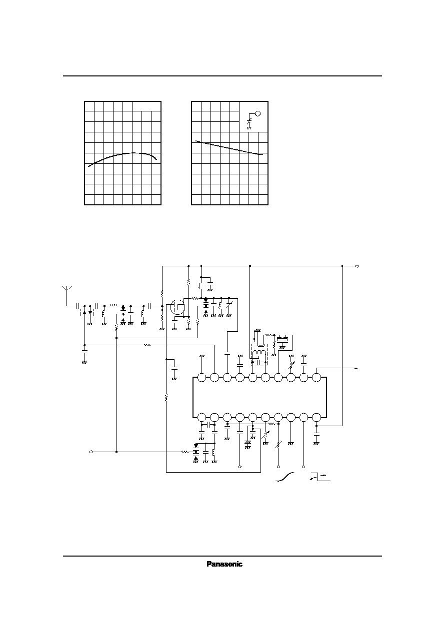
Characteristics Curve
Level ∑ Diagram
50
40
30
20
10
0
L
e
v
e
l
(
d
B
)
V
CC
=8V
f
in
=98MHz
Mod.=22.5kHz
f
m
=1kHz
IF : AN7256
400Hz HPF ON
Input/Output Characteristics
Frequency Change
0
≠20
≠40
≠60
≠80
V
in
(dB
µ
V)
A
F
O
U
T
(
d
B
)
40
0
20
80
60
24.5
13.5
8.5
43.5 (max.)
20
15
10
5
0
≠5
≠10
≠15
f
in
(MHz)
V
i
n
(
d
B
µ
V
)
98
96
90
88
94
92
106 108
104
102
100
V
CC
=8V
f
in
=1kHz
Mod.=22.5kHz
IF : AN7256
Mix.
IF
OUT
0.01
µ
F
MS3
080
IN
IFT
330
IF≠Amp.
16.0 (min.)
Practical Sensitivity (S/N=30dB)
Limiting Sensitivity
Residual Noise

ICs for FM/AM Tuner
AN7280S
No Input
IF-Amp. Gain Adjustment
40
30
20
10
0
Pin13 Adjusting Resistance (
)
G
a
i
n
(
d
B
)
0
1k
10K
V
CC
= 8V
f
in
= 18MHz
Radj. is Piny external resistance
(AGC Start Point Variable)
AGC ON Level
110
100
90
80
70
60
50
0
Pin7 V
cont in
(V)
V
i
n
(
d
B
µ
V
)
2.2
0
1.4
1
1.8
4
Radj.=
No Input
Supply Voltage Dependence
35
30
25
20
15
10
5
0
5
4
3
2
1
0
V
CC
(V)
I
t
o
t
(
m
A
)
V
r
e
f
(
V
)
6
0
2
4
12
10
8
Supply Voltage Change
110
100
60
50
20
10
0
V
CC
(V)
V
i
n
(
d
B
µ
V
)
8
6
7
10
9
V
CC
= 8V
f
in
= 98MHz No Adjustment
Pin7
= HIGH
Pin9 =
High
Pin9 = Low
Local Oscillation Level
AGC ON Level
Practical Sensitivity
Limiting Sensitivity
Total Gain
Temperature Characteristics
10
8
6
4
2
0
≠2
≠4
≠6
≠8
≠10
Ta (∞C)
T
o
t
a
l
G
a
i
n
(
d
B
)
20
40
0
≠40
≠20
100
60
80
0dB= 43.5dB
V
ref
I
tot
Supply Voltage Dependence
11
10
9
8
7
6
5
4
5
4
3
2
1
0
V
CC
(V)
A
G
C
O
U
T
V
t
(
V
)
S
S
C
O
N
L
e
v
e
l
(
V
)
8
5
6
7
11
12
10
9
SSC ON Level
V
t
IC for IF/DET
is normal temperature
Mixer+IF≠Amp.
V
CC
= 8V
Temperature Characteristics
80
70
60
50
40
30
20
10
0
Ta (∞C)
V
i
n
(
d
B
µ
V
)
0
≠60 ≠40 ≠20
60
80 100
40
20
Practical Sensitivity (S/N=30dB)
Limiting Sensitivity
AGC ON Level (max. Gain)
AGC Start Point
Temperature Characteristics
105
100
95
90
85
80
75
70
65
60
55
Ta (∞C)
V
i
n
(
d
B
µ
V
)
20
40
0
≠40
≠20
100
60
80
Pin7=1V
Pin6=GND
Pin9=OPEN
Pin7=HIGH
Pin6=GND
Pin9=OPEN
Pin7=HIGH
Pin6=OPEN
Pin9=5V
Pin7=HIGH
Pin6=OPEN
Pin9=OPEN
f=10.7MHz
13
IF Amp.
Input
Output
330
27dB
Radj.= 0
Amp. Gain Adjustment
with AGC
110
100
90
80
70
60
50
Pin6 Adjusting Resistance (
)
A
G
C
O
N
L
e
v
e
l
(
d
B
µ
V
)
0
1k
10K
AN7280S
ICs for FM/AM Tuner
IF Amp. Output Saturation Level
Temperature Characteristics
5
4
3
2
1
0
≠1
≠2
≠3
≠4
≠5
Ta (∞C)
I
F
A
m
p
.
O
u
t
p
u
t
S
a
t
u
r
a
t
i
o
n
L
e
v
e
l
(
d
B
)
20
40
0
≠40
≠20
100
60
80
V
CC
=8V
SSC ON Level
Temperature Characteristics
5
4
3
2
1
0
Ta (∞C)
P
i
n
o
V
o
l
t
a
g
e
(
V
)
20
40
0
≠40
≠20
100
60
80
SSC Input Pin
9
20
1
19
2
18
3
17
4
16
5
15
6
14
7
13
8
12
9
11
10
GND
PIN
D
AGC
RF
IN
Pass
Con.
Mix
OUT
Mix
OUT
IF
IN
IF
Gain
Adj
Pass
Con.
IF
OUT
E
B
Pass
C
OSC
OUT AGC
2 Loop
IN
GND SSC
V
CC
AGC
Gain
Adj
AN7280S
≠
+
KVC≠1340
120k
3
p
F
1
2
p
F
56pF
5
6
p
F 0.
0
1
µ
F
0
.
0
0
1
µ
F
1
µ
F
0
.
0
1
µ
F
180k
0
.
0
1
µ
F
To IF
0
.
0
1
µ
F
0
.
0
1
µ
F
4
p
F
4
7
0
330
C≠F
0
.
0
1
µ
F
1k
0
.
0
0
1
µ
F
1
5
p
F
0
.
0
1
µ
F
1
2
p
F
8
2
0
22
3
3
0
1
0
0
k
1
0
0
k
8
2
k
18pF
3SK1311
KVC≠1340
1
0
0
k
18pF
0.001
µ
F
MA551
ANT
KVC≠1340
1
0
0
k
V
T
0V
0V
5V 5V
Control
Voltage
At Search
At Normal
Produced by MATSUSHITA
IFT : ZIF≠5EF021B
V
CC
s
Application Circuit

ICs for FM/AM Tuner
AN7280S
s
Pin Descriptions
Equivalent Circuit
Pin Name
Pin No.
Description
1
OSC Emitter
Local oscillation transistor emitter pin
2
OSC Base
Local oscillation transistor base pin
3
OSC By-pass
4
OSC Buffer Output
Pin for output OSC signal to pre-scaler
5
Level Detection Output
6
AGC≠ Amp. Gain Adjustment
7
Control Signal Input
8
GND
9
SSC Input
10
V
CC
AGC signal output pin for RF-Amp.
secondary gate
Pin for adjusting AGC Amp. gain by
external resistance
Pin for adjusting AGC-Amp. gain through
input of control signal from IF section
Pin for adjusting AGC-Amp. gain through
input of control signal from microcomputer
V
ref
by-pass pin for mixer,OSC buffer,OSC
section
2
1
V
ref
4
V
ref
750
5
V
CC
.70
µ
A
6
5.6k
7
1.5k
1.5V
V
ref
9
70k
39k
≠
+
3
5V

AN7280S
ICs for FM/AM Tuner
s
Pin Descriptions (Cont.)
Equivalent Circuit
Pin Name
Pin No.
Description
12
IF-Amp. By-pass
IF-Amp. by-pass pin
14
IF-Amp. Input
IF-Amp. input pin
15
16
11
IF-Amp.
IF-Amp. output pin
Mix. Output
19
ADX Output
20
GND
Oscillator GND
PIN diode driver output pin
Determine maximum current to PIN diode
by Pin19 external resistance value.
17
Mix. By-pass
Mixer by-pass pin
18
Mix. Input
Mixer input pin
13
IF-Amp. Gain Adjustment
Pin for adjusting IF-Amp. gain by external
resistance
Mixer output pin
V
CC
11
240
3k
Z
OUT
.300
12
14
330
13
12k
340
15
16
17
18
2.2k
2.2k
19

ICs for FM/AM Tuner
AN7280S
s
Operational Description
∑ Loop AGC
The AN7280S uses 2Loop AGC for AGC circuit. 2Loop AGC controls AGC output by using mixer output (IFT first side)
signal and FM≠IF control voltage (level meter output), which is a very favorable system for disturbance characteristics,
etc.
RF≠Amp.
Mixer
IFT
IF≠Amp.
Control Voltage Output
To N.C.
∑
AGC start point (Mixer input level at V
AGC
< 3V) changes in proportion to Pin6 external resistance (following R
1
) , Pin
7 applied voltage (Determine IF control voltage by R
2
, R
3
resistance division) SSC ON/OFF
∑ Variable width at R
1
28dB (however, V
7
3V, V
9
= 0V)
∑ Variable width at R
7
40dB (however, R
1
=
, V
9
= 0V)
∑ Variable width at R
9
10dB (however, R
1
=
, V
7
3V)
3
V
AGC
about 4.7V
5
6
7
9
R
1
R
2
R
3
V
REF
AGC Output
AGC≠Adj
Vcont IN
SSC IN
from microcomputer
FM≠IF
Control voltage
∑ SSC
Change AGC start point by microcomputer control signal at seek/reception time.
Use at SSC ON ∑∑∑∑∑∑∑∑V
9
> 3.5V
Use at SSC OFF∑∑∑∑∑∑∑∑V
9
< 1.5V
* SSC is designed as precondition for switching operation at microcomputer control signal.
FM≠IF
AGC
Amp.
AGC
Det.