2002 Feb 28
2
Philips Semiconductors
Product specification
Voltage regulator diodes
BZV55 series
FEATURES
∑
Total power dissipation: max. 500 mW
∑
Two tolerance series:
±
2%, and approx.
±
5%
∑
Working voltage range: nom. 2.4 to 75 V (E24 range)
∑
Non-repetitive peak reverse power dissipation:
max. 40 W.
APPLICATIONS
∑
Low voltage stabilizers or voltage references.
DESCRIPTION
Low-power voltage regulator diodes in small hermetically
sealed glass SOD80C SMD packages. The diodes are
available in the normalized E24
±
2% (BZV55-B) and
approx.
±
5% (BZV55-C) tolerance range. The series
consists of 37 types with nominal working voltages from
2.4 to 75 V.
columns
MAM215
k
a
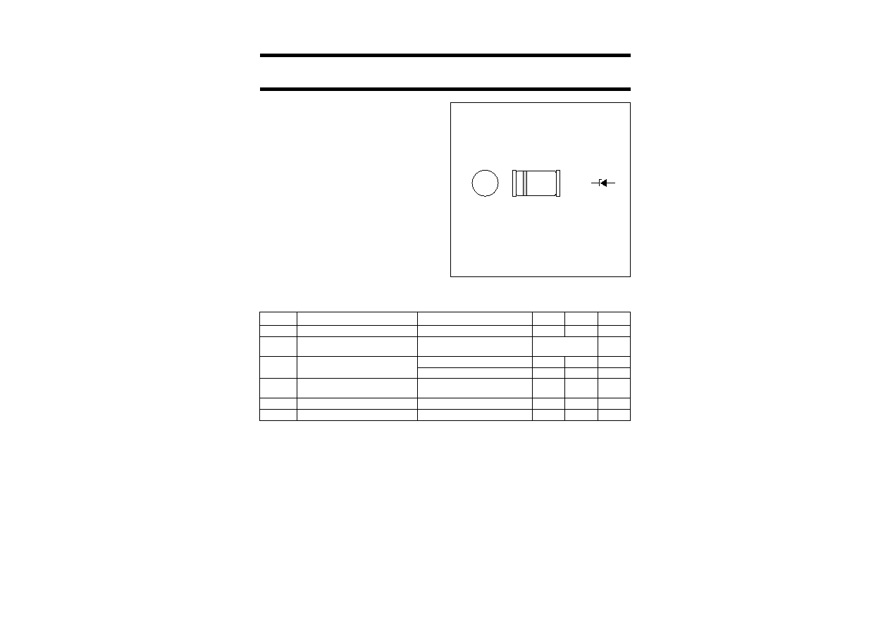
Fig.1
Simplified outline (SOD80C) and symbol.
The cathode is indicated by a yellow band.
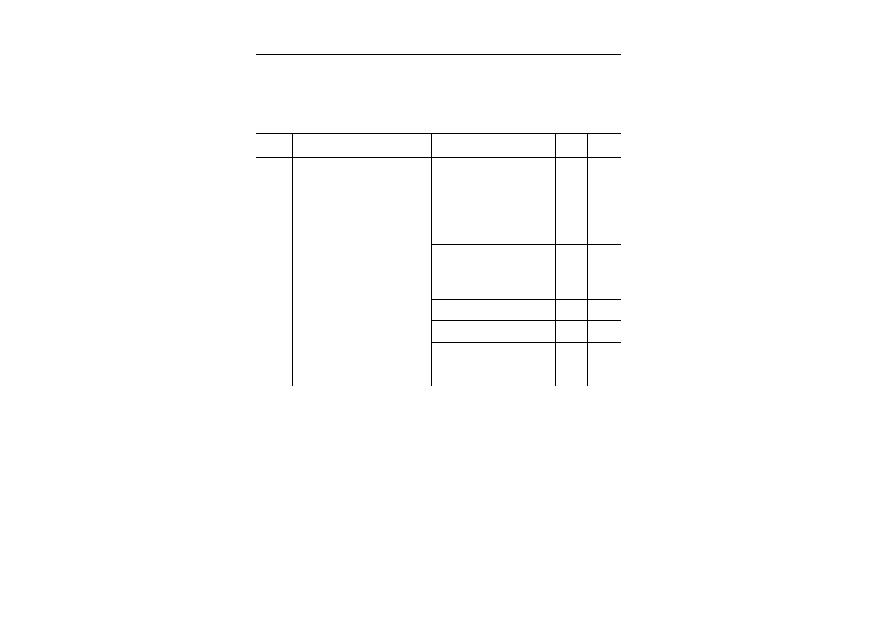
LIMITING VALUES
In accordance with the Absolute Maximum Rating System (IEC 60134).
Note
1. Device mounted on a ceramic substrate of 10
◊
10
◊
0.6 mm.
SYMBOL
PARAMETER
CONDITIONS
MIN.
MAX.
UNIT
I
F
continuous forward current
-
250
mA
I
ZSM
non-repetitive peak reverse current
t
p
= 100
µ
s; square wave;
T
j
= 25
∞
C prior to surge
see Tables 1 and 2 A
P
tot
total power dissipation
T
amb
50
∞
C; note 1
-
400
mW
tie-point
50
∞
C; note 1
-
500
mW
P
ZSM
non-repetitive peak reverse power
dissipation
t
p
= 100
µ
s; square wave;
T
j
= 25
∞
C prior to surge; see Fig.3
-
40
W
T
stg
storage temperature
-
65
+200
∞
C
T
j
junction temperature
-
65
+200
∞
C
2002 Feb 28
3
Philips Semiconductors
Product specification
Voltage regulator diodes
BZV55 series
ELECTRICAL CHARACTERISTICS
Total BZV55-B and BZV55-C series
T
j
= 25
∞
C; unless otherwise specified.
SYMBOL
PARAMETER
CONDITIONS
MAX.
UNIT
V
F
forward voltage
I
F
= 10 mA; see Fig.4
0.9
V
I
R
reverse current
BZV55-B/C2V4
V
R
= 1 V
50
µ
A
BZV55-B/C2V7
V
R
= 1 V
20
µ
A
BZV55-B/C3V0
V
R
= 1 V
10
µ
A
BZV55-B/C3V3
V
R
= 1 V
5
µ
A
BZV55-B/C3V6
V
R
= 1 V
5
µ
A
BZV55-B/C3V9
V
R
= 1 V
3
µ
A
BZV55-B/C4V3
V
R
= 1 V
3
µ
A
BZV55-B/C4V7
V
R
= 2 V
3
µ
A
BZV55-B/C5V1
V
R
= 2 V
2
µ
A
BZV55-B/C5V6
V
R
= 2 V
1
µ
A
BZV55-B/C6V2
V
R
= 4 V
3
µ
A
BZV55-B/C6V8
V
R
= 4 V
2
µ
A
BZV55-B/C7V5
V
R
= 5 V
1
µ
A
BZV55-B/C8V2
V
R
= 5 V
700
nA
BZV55-B/C9V1
V
R
= 6 V
500
nA
BZV55-B/C10
V
R
= 7 V
200
nA
BZV55-B/C11
V
R
= 8 V
100
nA
BZV55-B/C12
V
R
= 8 V
100
nA
BZV55-B/C13
V
R
= 8 V
100
nA
BZV55-B/C15 to BZV55-B/C75
V
R
= 0.7V
Znom
50
nA
2002
Feb
28
4
Philips Semiconductors
Product specification
V
oltage regulator diodes
BZV55 ser
ies
2002
Feb
28
4
Philips Semiconductors
Product specification
V
oltage regulator diodes
BZV55 ser
ies
This text is here in white to force landscape pages to be rotated correctly when browsing through the pdf in the Acrobat reader.This text is here in
_
white to force landscape pages to be rotated correctly when browsing through the pdf in the Acrobat reader.This text is here inThis text is here in
white to force landscape pages to be rotated correctly when browsing through the pdf in the Acrobat reader. white to force landscape pages to be ...
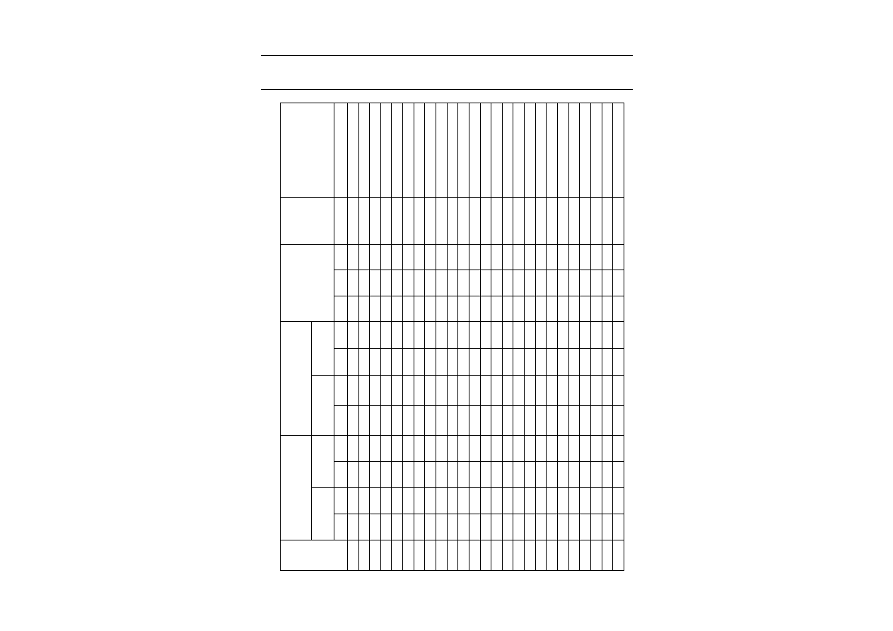
Table 1
Per type, BZV55-B/C2V4 to BZV55-B/C24
T
j
= 25
∞
C unless otherwise specified.
BZV55-
Bxxx
Cxxx
WORKING VOLTAGE
V
Z
(V)
at I
Ztest
= 5 mA
DIFFERENTIAL RESISTANCE
r
dif
(
)
TEMP. COEFF.
S
Z
(mV/K)
at I
Ztest
= 5 mA
(see Figs 5 and 6)
DIODE CAP.
C
d
(pF)
at f = 1 MHz;
V
R
= 0 V
NON-REPETITIVE PEAK
REVERSE CURRENT
I
ZSM
(A)
at t
p
= 100
µ
s; T
amb
= 25
∞
C
Tol.
±
2% (B)
Tol. approx.
±
5% (C)
at I
Ztest
= 1 mA
at I
Ztest
= 5 mA
MIN.
MAX.
MIN.
MAX.
TYP.
MAX.
TYP.
MAX.
MIN.
TYP.
MAX.
MAX.
MAX.
2V4
2.35
2.45
2.2
2.6
275
600
70
100
-
3.5
-
1.6
0
450
6.0
2V7
2.65
2.75
2.5
2.9
300
600
75
100
-
3.5
-
2.0
0
450
6.0
3V0
2.94
3.06
2.8
3.2
325
600
80
95
-
3.5
-
2.1
0
450
6.0
3V3
3.23
3.37
3.1
3.5
350
600
85
95
-
3.5
-
2.4
0
450
6.0
3V6
3.53
3.67
3.4
3.8
375
600
85
90
-
3.5
-
2.4
0
450
6.0
3V9
3.82
3.98
3.7
4.1
400
600
85
90
-
3.5
-
2.5
0
450
6.0
4V3
4.21
4.39
4.0
4.6
410
600
80
90
-
3.5
-
2.5
0
450
6.0
4V7
4.61
4.79
4.4
5.0
425
500
50
80
-
3.5
-
1.4
0.2
300
6.0
5V1
5.00
5.20
4.8
5.4
400
480
40
60
-
2.7
-
0.8
1.2
300
6.0
5V6
5.49
5.71
5.2
6.0
80
400
15
40
-
2.0
1.2
2.5
300
6.0
6V2
6.08
6.32
5.8
6.6
40
150
6
10
0.4
2.3
3.7
200
6.0
6V8
6.66
6.94
6.4
7.2
30
80
6
15
1.2
3.0
4.5
200
6.0
7V5
7.35
7.65
7.0
7.9
30
80
6
15
2.5
4.0
5.3
150
4.0
8V2
8.04
8.36
7.7
8.7
40
80
6
15
3.2
4.6
6.2
150
4.0
9V1
8.92
9.28
8.5
9.6
40
100
6
15
3.8
5.5
7.0
150
3.0
10
9.80
10.20
9.4
10.6
50
150
8
20
4.5
6.4
8.0
90
3.0
11
10.80
11.20
10.4
11.6
50
150
10
20
5.4
7.4
9.0
85
2.5
12
11.80
12.20
11.4
12.7
50
150
10
25
6.0
8.4
10.0
85
2.5
13
12.70
13.30
12.4
14.1
50
170
10
30
7.0
9.4
11.0
80
2.5
15
14.70
15.30
13.8
15.6
50
200
10
30
9.2
11.4
13.0
75
2.0
16
15.70
16.30
15.3
17.1
50
200
10
40
10.4
12.4
14.0
75
1.5
18
17.60
18.40
16.8
19.1
50
225
10
45
12.4
14.4
16.0
70
1.5
20
19.60
20.40
18.8
21.2
60
225
15
55
12.3
15.6
18.0
60
1.5
22
21.60
22.40
20.8
23.3
60
250
20
55
14.1
17.6
20.0
60
1.25
24
23.50
24.50
22.8
25.6
60
250
25
70
15.9
19.6
22.0
55
1.25
2002
Feb
28
5
Philips Semiconductors
Product specification
V
oltage regulator diodes
BZV55 ser
ies
2002
Feb
28
5
Philips Semiconductors
Product specification
V
oltage regulator diodes
BZV55 ser
ies
This text is here in white to force landscape pages to be rotated correctly when browsing through the pdf in the Acrobat reader.This text is here in
_
white to force landscape pages to be rotated correctly when browsing through the pdf in the Acrobat reader.This text is here inThis text is here in
white to force landscape pages to be rotated correctly when browsing through the pdf in the Acrobat reader. white to force landscape pages to be ...
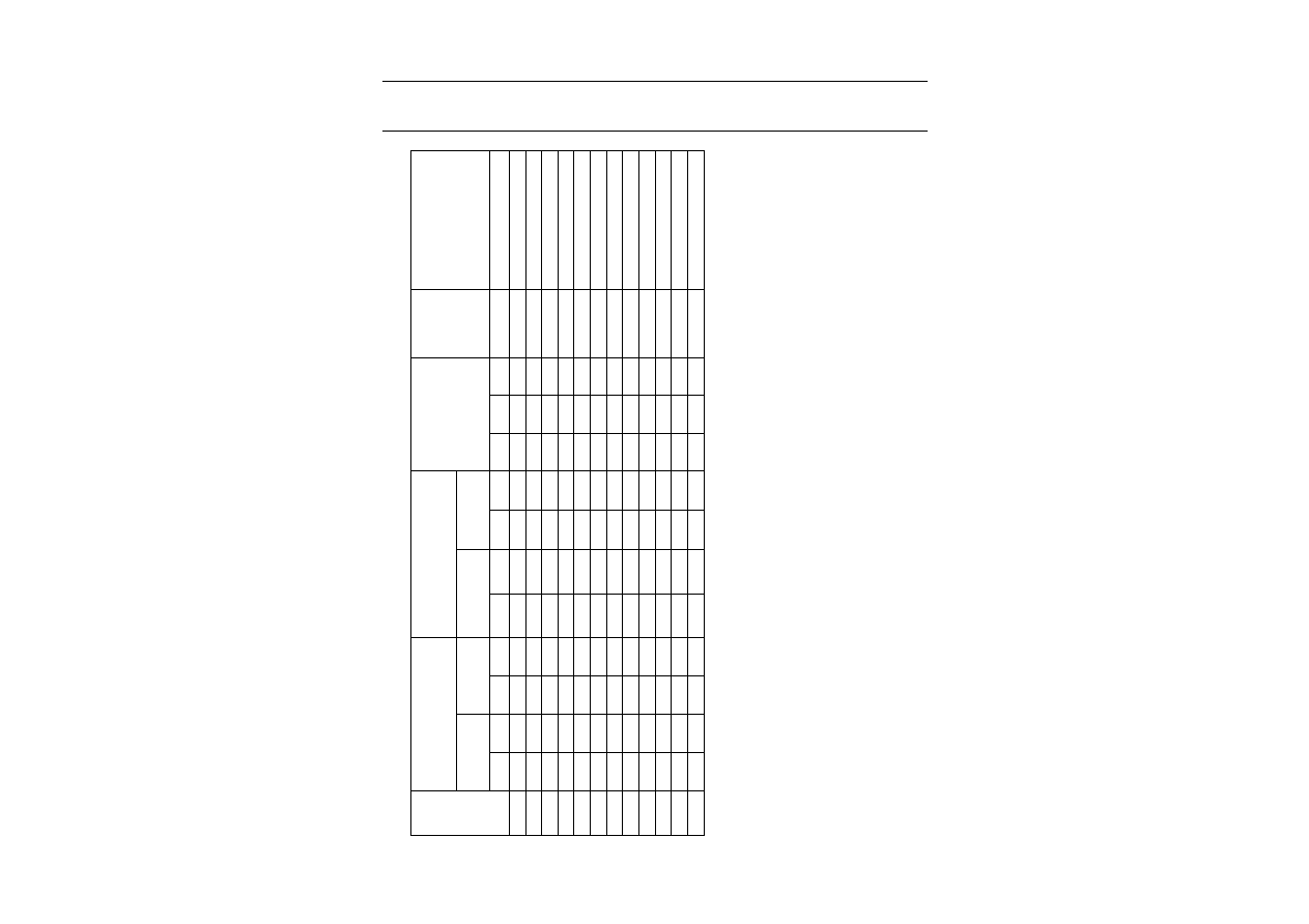
Table 2
Per type, BZV55-B/C27 to BZV55-B/C75
T
j
= 25
∞
C unless otherwise specified.
BZV55-
Bxxx
Cxxx
WORKING VOLTAGE
V
Z
(V)
at I
Ztest
= 2 mA
DIFFERENTIAL RESISTANCE
r
dif
(
)
TEMP. COEFF.
S
Z
(mV/K)
at I
Ztest
= 2 mA
(see Figs 5 and 6)
DIODE CAP.
C
d
(pF)
at f = 1 MHz;
V
R
= 0 V
NON-REPETITIVE PEAK
REVERSE CURRENT
I
ZSM
(A)
at t
p
= 100
µ
s; T
amb
= 25
∞
C
Tol.
±
2% (B)
Tol. approx.
±
5% (C)
at I
Ztest
= 0.5 mA at I
Ztest
= 2 mA
MIN.
MAX.
MIN.
MAX.
TYP.
MAX.
TYP.
MAX.
MIN.
TYP.
MAX.
MAX.
MAX.
27
26.50
27.50
25.1
28.9
65
300
25
80
18.0
22.7
25.3
50
1.0
30
29.40
30.60
28.0
32.0
70
300
30
80
20.6
25.7
29.4
50
1.0
33
32.30
33.70
31.0
35.0
75
325
35
80
23.3
28.7
33.4
45
0.9
36
35.30
36.70
34.0
38.0
80
350
35
90
26.0
31.8
37.4
45
0.8
39
38.20
39.80
37.0
41.0
80
350
40
130
28.7
34.8
41.2
45
0.7
43
42.10
43.90
40.0
46.0
85
375
45
150
31.4
38.8
46.6
40
0.6
47
46.10
47.90
44.0
50.0
85
375
50
170
35.0
42.9
51.8
40
0.5
51
50.00
52.00
48.0
54.0
90
400
60
180
38.6
46.9
57.2
40
0.4
56
54.90
57.10
52.0
60.0
100
425
70
200
42.2
52.0
63.8
40
0.3
62
60.80
63.20
58.0
66.0
120
450
80
215
58.8
64.4
71.6
35
0.3
68
66.60
69.40
64.0
72.0
150
475
90
240
65.6
71.7
79.8
35
0.25
75
73.50
76.50
70.0
79.0
170
500
95
255
73.4
80.2
88.6
35
0.2
