 | ÐлекÑÑоннÑй компоненÑ: HTRM800 | СкаÑаÑÑ:  PDF PDF  ZIP ZIP |
Äîêóìåíòàöèÿ è îïèñàíèÿ www.docs.chipfind.ru

DATA SHEET
Product specification
Supersedes data of 1999 Jan 01
File under Integrated Circuits, IC11
2001 Oct 04
INTEGRATED CIRCUITS
HTRM800 family
HITAG long range reader module
hardware

2001 Oct 04
2
Philips Semiconductors
Product specification
HITAG long range reader module
hardware
HTRM800 family
CONTENTS
1
FEATURES
2
APPLICATIONS
3
GENERAL DESCRIPTION
4
ORDERING INFORMATION
5
BLOCK DIAGRAM
6
PINNING
6.1
ST1 connector
6.2
ST2 connector
7
FUNCTIONAL DESCRIPTION
7.1
System overview
7.1.1
Transponders
7.1.2
Antenna
7.1.3
Host system
7.1.4
I/O functions
7.1.5
Power supply
7.2
Reader module software
7.3
Reader module hardware
7.3.1
Microcontroller
7.3.2
Interface microcontroller to host
7.3.3
Transmitting part
7.3.4
Receiving part
7.3.5
Digital signal processing unit
7.3.6
Periodic disturbers
7.3.7
Voltage regulating unit
7.3.8
Standby mode
7.3.9
Behaviour with HITAG 1 transponders
7.3.10
Behaviour with HITAG 2 transponders
7.4
Postal approval
7.5
Operating security
7.5.1
Anticollision mode
7.5.2
Monitoring the supply voltage
7.5.3
Antenna rupture and antenna short-circuit
7.6
Security considerations
7.6.1
Data privacy
8
ELECTRICAL SPECIFICATIONS
9
MECHANICAL SPECIFICATIONS
10
APPLICATION INFORMATION
10.1
Metallic environment and interferences
10.2
Distance between two antennas
10.3
External power supply
10.4
Possible sources of errors by connecting the
HTRM800
10.5
Building HITAG long range antennas
10.5.1
Basics
10.5.2
Recommended antenna cable and length
10.5.3
Tuning of the antenna current
10.5.4
Tuning of the antenna phase
10.5.5
HITAG antenna tuning device
10.5.6
Antenna malfunction indication
10.5.7
Additional remarks
10.6
Antenna arrangements
11
SURVEY OF REFERENCED DOCUMENTS
12
DATA SHEET STATUS
13
DEFINITIONS
14
DISCLAIMERS

2001 Oct 04
3
Philips Semiconductors
Product specification
HITAG long range reader module
hardware
HTRM800 family
1
FEATURES
·
Multi-tag operation (anticollision)
·
Read and write distances up to 1000 mm
·
Digital signal processor to reduce noise sensitivity
·
Communication with all HITAG transponders and
various other 125 kHz transponders
·
Data encryption and key handling
·
Easy system integration
·
Three interface options
·
Meets all requirements for CE and EMI approval.
2
APPLICATIONS
·
Universal and flexible reader module for long range
systems.
3
GENERAL DESCRIPTION
HITAG
(1)
is the name of one of the universal and powerful
product lines of our 125 kHz family. The contactless read
and write system that works with passive transponders is
suitable for various applications.
Inductive coupling helps you to achieve operating ranges
up to 1000 mm and the use of cryptography guarantees
highest data security.
Anticollision mode, which is used only in long range
operation, allows you to handle several transponders that
are within the communication field of the antenna at the
same time, thus achieving highest operating security and
permitting to handle several data transfers quickly and
simultaneously. In this context anticollision becomes an
essential element of applications such as ski-ticketing and
long range access control. With applications of that type it
will always happen that several transponders arrive in the
communication field of the antenna at the same time.
(1) HITAG - is a trademark of Philips Semiconductors
Gratkorn GmbH.
4
ORDERING INFORMATION
PART NUMBER
NAME
ORDER CODE (12NC)
HTRM800/AED
HITAG long range reader module RS232
9352 338 40122
HTRM800/CED
HITAG long range reader module RS485
9352 338 50122
HTRM800/EED
HITAG long range reader module CMOS
9352 338 60122
2001 Oct 04
4
Philips Semiconductors
Product specification
HITAG long range reader module
hardware
HTRM800 family
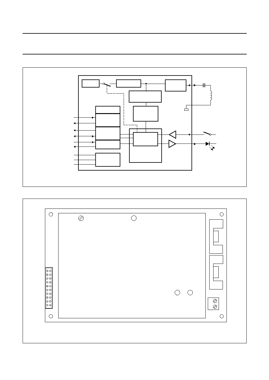
5
BLOCK DIAGRAM
handbook, full pagewidth
AMPLIFIER
HTRM800
VOLTAGE
LIMITER
ANT
GND
C
L
antenna
MGU417
CMIN
CMOUT
FILTER
DEMODULATOR
DIGITAL
SIGNAL
PROCESSOR
125 kHz
LINE DRIVER
RS232
CMOSIN
CMOSOUT
INT1
INT2
RXD
TXD
+
15 V IN
GND
-
15 V IN
CMOS
OPTIONAL
RS485
OPTIONAL
MICRO-
CONTROLLER
CORE MODULE
HTCM400
VOLTAGE
REGULATOR
Fig.1 Block diagram.
6
PINNING
handbook, full pagewidth
MGU418
11
20
ST2
2
1
ANT
GND
ST1
R72
HTRM800
10
1
Fig.2 Pin assignment.

2001 Oct 04
5
Philips Semiconductors
Product specification
HITAG long range reader module
hardware
HTRM800 family
6.1
ST1 connector
Note
1. P = power supply, O = output and I = input.
6.2
ST2 connector
SYMBOL
PIN
TYPE
(1)
DESCRIPTION
-
15VIN
1
P
DC supply voltage (
-
15 V)
GND
2
P
ground
+
15VIN
3
P
DC supply voltage (+15 V)
GND
4
P
ground
RXD
5
I
serial interface input; RS232 level
GND
6
P
ground
CMOSIN
7
I
serial interface input; CMOS level (optional)
INT1
8
I/O
serial interface input and output 1; RS485 level (optional)
CMIN
9
I
core module input; general purpose
CMOUT
10
O
core module output; general purpose
GND
11
P
ground
GND
12
P
ground
INT2
13
I/O
serial interface input and output 2; RS485 level (optional)
CMOSOUT
14
O
serial interface output; CMOS level (optional)
GND
15
P
ground
TXD
16
O
serial interface output; RS232 level
GND
17
P
ground
+
15VIN
18
P
DC supply voltage (+15 V)
GND
19
P
ground
-
15VIN
20
P
DC supply voltage (
-
15 V)
SYMBOL
PIN
DESCRIPTION
GND
1
ground
ANT
2
antenna output and input
2001 Oct 04
6
Philips Semiconductors
Product specification
HITAG long range reader module
hardware
HTRM800 family
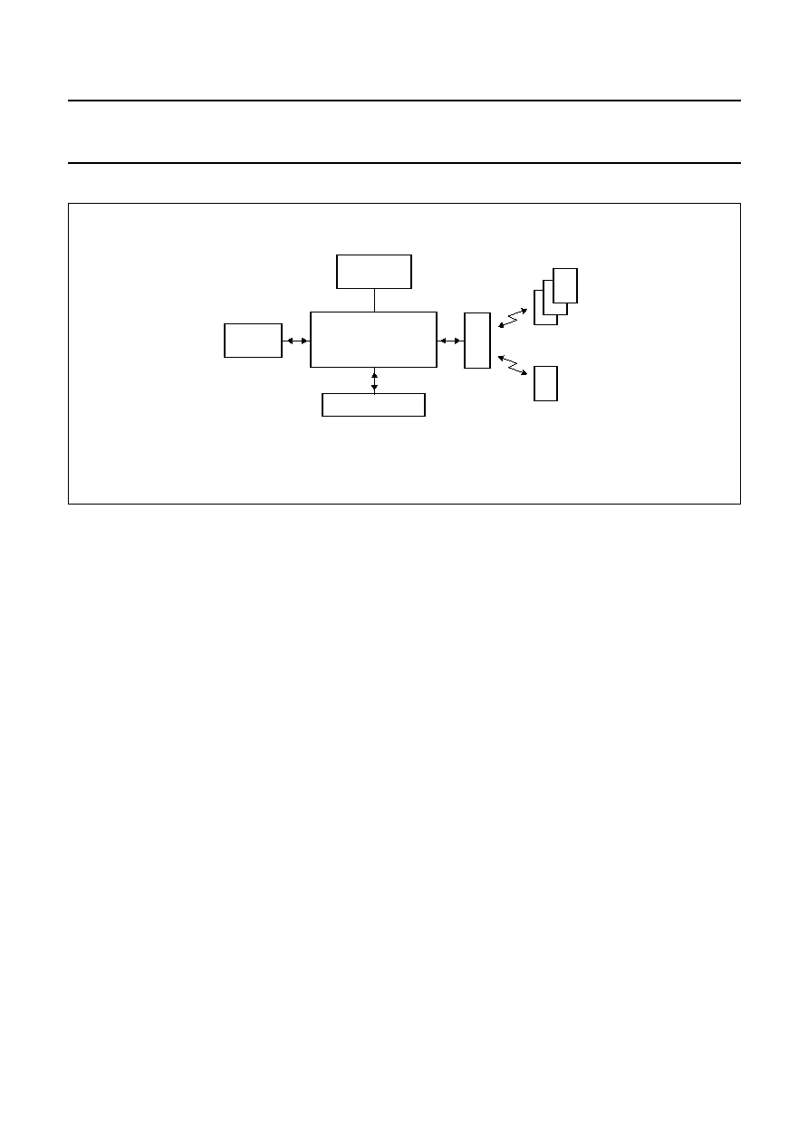
7
FUNCTIONAL DESCRIPTION
handbook, full pagewidth
HTRM800
I/O FUNCTIONS
MGU419
HOST
SYSTEM
antenna
HITAG 1
transponders
HITAG 2
transponder
POWER
SUPPLY
Fig.3 System overview.
7.1
System overview
The HITAG long range reader module (see Fig.3) is a part
of a complete Radio Frequency Identification (RFID)
system which consists of:
·
Transponders
·
Antenna
·
Host system
·
I/O functions
·
Power supply.
7.1.1
T
RANSPONDERS
The HTRM800 can communicate with transponders based
on Philips HITAG 1 and HITAG 2.
7.1.2
A
NTENNA
The antenna is an important part of the HITAG long range
system. The antenna must provide energy and data
transmission between the reader module and transponder.
7.1.3
H
OST SYSTEM
The connection to the host system (e.g. microcontroller
or PC) is a serial interface on RS232 level for data
transmission.
7.1.4
I/O
FUNCTIONS
One line of the HTRM800 is wired as input from e.g. a
switch and one line as output to drive a LED.
7.1.5
P
OWER SUPPLY
The HTRM800 must be supplied from an external power
supply with +15 V and
-
15 V (see Section 10.3).
7.2
Reader module software
Software command names mentioned in this data sheet
are fully described in document
"HTCM400, HTRM440
Family, HTRM800 Family Interface Protocol Reader -
Host".
7.3
Reader module hardware
7.3.1
M
ICROCONTROLLER
The microcontroller is placed on the HITAG core module
(see Fig.1) and processes the protocol for the
communication between the transponders and the reader
module. The interface signals are converted so that the
transponders are able to process them and the outgoing
signals from the transponders are converted into
interface-compatible signals.
The second essential microcontroller function is its control
function. The microcontroller activates and deactivates the
transmitter and switches the receiver between the modes
for the different transponders reception.
Additional functions of the microcontroller are controlling
the standby mode of the amplifier, detection of detuned or
broken antennas (antenna malfunction) and controlling of
the input and output for general purpose.

2001 Oct 04
7
Philips Semiconductors
Product specification
HITAG long range reader module
hardware
HTRM800 family
7.3.2
I
NTERFACE MICROCONTROLLER TO HOST
The device communicates with the host system via a serial
interface using a baud rate of 9600 baud. Data transfer
details are: 1 start bit, 8 data bits, 1 stop bit, no parity bit
and the least significant bit is sent first.
Version HTRM800/AED has an integrated RS232 level
driver. Version HTRM800/CED is wired with an RS485
level driver and version HTRM800/EED is wired with a
CMOS level driver.
7.3.3
T
RANSMITTING PART
For transmitting power and data to the transponder a
125 kHz sine signal is switched by the microcontroller and
amplified. The amplifier is designed as a current source.
A voltage limiter is used to clamp the output voltage of the
amplifier during the decay and transient phases of the sine
signal.
7.3.4
R
ECEIVING PART
After filtering and demodulation of the amplitude
modulated signal received from the transponder, the
received data is converted and passed to the Digital Signal
Processing (DSP) unit for further processing.
7.3.5
D
IGITAL SIGNAL PROCESSING UNIT
The receiving part of the reader module includes
bandpass filters which attenuate disturbances (3 dB
attenuation at 105 and 145 kHz). For disturber
frequencies near the 125 kHz (e.g. harmonics of the line
frequency of PC monitors, long wave transmitters) a
fourier transformation is used to recognize harmonic
disturbers and to eliminate their influence. The DSP is also
responsible for separating the responses of different
transponders during anticollison cycles (multiple
transponder operation).
7.3.6
P
ERIODIC DISTURBERS
There are a couple of possible sources for disturbances for
a 125 kHz system like HITAG. The HTRM800 is designed
to handle this problem and achieve optimal performance
under worst conditions.
Long wave transmitters, other 125 kHz systems and
PC monitors are examples for periodic disturbers which
can be relevant for 125 kHz systems. To eliminate these
disturbers the digital signal processing unit is used.
After the command StartFFT is sent to the reader module
a Fast Fourier Transformation (FFT) is started to locate
periodic disturbers. After about 110 ms this calculation is
finished and for the following communication between
reader module and transponder the located disturbers are
eliminated. The command StartFFT should be executed
as often as the application allows.
Remarks:
1. The DSP is able to suppress up to two harmonic
electromagnetic disturbances
2. During FFT is running (about 110 ms) communication
with a transponder is not possible.
7.3.7
V
OLTAGE REGULATING UNIT
The reader module contains some filtering circuits which
supply all parts of the reader module with the required
voltages. Nevertheless some requirements are to be
fulfilled by the external power supply. This means the
maximum ripple of the supply voltages must not exceed
the values specified in Chapter 8.
7.3.8
S
TANDBY MODE
The HTRM800 offers a software controlled standby mode.
This mode can be activated and deactivated by the host
system. During the standby mode the amplifier is turned off
and the power consumption decreases drastically.
7.3.9
B
EHAVIOUR WITH
HITAG 1
TRANSPONDERS
If several HITAG 1 transponders arrive simultaneously
within the communication field of the antenna of a
HTRM800, all the transponders (theoretically up to 2
32
)
within the communication field of the antenna can be read
and written simultaneously. Because of the mutual
influence of the transponder coils - they detune each other
if there are too many too close to each other - the number
of the transponders that can be operated simultaneously is
limited.
7.3.10
B
EHAVIOUR WITH
HITAG 2
TRANSPONDERS
If several HITAG 2 transponders arrive simultaneously
within the communication field of the antenna of a
HTRM800, the `stronger' transponder (the nearer one)
takes over or - under special circumstances - no
communication takes place. If the transponders arrive in
the field one after the other, communication is established
with the first one, all the other transponders are ignored.
This ensures that no two (or several) HITAG 2
transponders will ever be processed (above all written to!)
accidentally at the same time. By muting a selected
HITAG 2 transponder (HALT mode) another HITAG 2
transponder that is to be found in the communication field
of the antenna can be recognized.

2001 Oct 04
8
Philips Semiconductors
Product specification
HITAG long range reader module
hardware
HTRM800 family
7.4
Postal approval
The postal approval can only be granted for final products,
not just for components like the HTRM800. But this reader
module is designed in a way that it is possible to get the
postal approval for a system including the HTRM800.
Electromagnetic emissions comply with the guidelines in
FTZ 17 TR 2100, ETS 300 330 and ETS 300 683.
Electromagnetic immunity complies with the guidelines in
ETS 300 683.
The following configuration is in compliance with the
European telecommunication standards:
·
Reader module HTRM800
·
Power supply according to the recommendations
(transformer type)
·
Antenna: 50
×
70 cm, number of turns N = 26 and
inductivity L = 1.2 mH.
A survey of the passed measurements is given in Table 1.
Table 1
Survey of measurements
ITEM
MEASUREMENT
STANDARD
REQUIREMENTS
EMI
electromagnetic emission
ETS 300 330, Sep 1994
FTZ 17 TR 2100
RFI emission limit class
EN 55022, 1987
Immunity
RF electromagnetic field
ENV 50140
80 to 1000 MHz: 3 V/m, AM 80%, 1 kHz
electrostatic discharge
IEC 801-2, 1991
contact discharge: 4 kV; air discharge: 8 kV
electrical fast transient
(burst)
IEC 801-4, 1988
signal ports: 0.5 kV; DC power ports: 1 kV;
AC power ports 2 kV
RF common mode
ENV 50141
current clamp injection 150 kHz to 80 MHz:
3 V (rms), AM 80%, 1 kHz
voltage dips and
interruptions
IEC 1000-4-11
reduction of 30% of UN for 10 ms, of 60% of
UN for 100 ms, voltage interruption for 5 s
surges, common and
differential mode
IEC 1000-4-5
AC power input ports: 1 kV
(lines-to-ground), 0.5 V (line-to-line)
7.5
Operating security
The following mechanisms ensure the operation security
of the HITAG system:
·
Anticollission mode
·
Monitoring the supply voltage
·
Antenna rupture and short circuit.
7.5.1
A
NTICOLLISION MODE
Anticollision mode in long range applications permits you
to process several HITAG 1 transponders simultaneously.
Theoretically up to 2
32
HITAG 1 transponders can be
processed simultaneously. In practice this number is
limited, because of the mutual influence of the
transponders. They detune each other, if there are too
many too close to each other. In long range applications
using HITAG 2 transponders, only one transponder is
handled even if there are several transponders within the
communication field of the antenna. In this case either no
communication takes place or the `stronger' or closer
transponder takes over.
By muting a selected transponder (HALT mode) another
transponder that is to be found in the communication field
of the antenna can be recognized.
7.5.2
M
ONITORING THE SUPPLY VOLTAGE
The supply voltage is controlled by a watch dog circuit
which triggers a system reset if the supply voltage of the
core module drops below 4.75 V or if the microcontroller
fails.
7.5.3
A
NTENNA RUPTURE AND ANTENNA SHORT
-
CIRCUIT
The HTRM800 does not get permanently damaged in case
of an antenna rupture or a brief antenna short-circuit. The
detection of detuned or broken antennas (antenna
malfunction) is possible.

2001 Oct 04
9
Philips Semiconductors
Product specification
HITAG long range reader module
hardware
HTRM800 family
7.6
Security considerations
Developing the HITAG system special consideration was
given to aspects of security. The following items represent
the fundamental framework of the security concept:
·
Cryptography
·
Mutual authentication
·
Password verification
·
Cyclic Redundancy Check (CRC).
7.6.1
D
ATA PRIVACY
The use of cryptography (stream cypher), mutual
authentication, and password verification prevents
monitoring and copying the data channel. Therefore, the
area of the transponder that only can be accessed
enciphered is called `secret area'.
To make use of cryptography for HITAG 1 transponders
you need:
·
Keys to be used for initializing of the crypto block
·
Logdata to be used for mutual authentication.
To make use of cryptography for HITAG 2 transponders
you need:
·
A key which is used to initialize the crypto block using
HITAG 2 in crypto mode
·
Passwords which are used for authentication for
HITAG 2 in password mode.
The transponders and the HTRM800 are provided with
identical transport keys and transport logdata so that you
can start operating them right away (see Table 2).
In order to offer our OEM clients high flexibility, the
configuration of the transponder memory, password, keys
and logdata can be changed. We strictly recommend to
rigorously restrict these possibilities for the end customers
(by setting the configuration page to read only, setting
password, keys and logdata to neither read nor write).
Table 2
Transport values predefined by Philips.
SYSTEM
PARAMETER
VALUE
HITAG 1
keyinit password
0x00000000
keys
0x00000000
logdata
0x00000000
HITAG 2
keyinit password
0x00000000
key
0x4D494B524F4E
password TAG
0xAA4854
password RWD
0x4D494B52
2001 Oct 04
10
Philips Semiconductors
Product specification
HITAG long range reader module
hardware
HTRM800 family
8
ELECTRICAL SPECIFICATIONS
Notes
1. Modulation type is Amplitude Shift Keying (ASK). A modulation ratio of 100% means the carrier is blanked
completely, the information is located in the intervals between the pauses.
2. Modulation type is Amplitude Shift Keying (ASK). The modulation ratio depends on the distance between
transponder and reader module.
SYMBOL
PARAMETER
CONDITIONS
MIN.
TYP.
MAX.
UNIT
Power supply
V
P1
positive supply voltage
-
15
-
V
I
P1
positive supply current
operating mode
-
400
550
mA
standby mode
-
200
-
mA
V
P2
negative supply voltage
-
-
15
-
V
I
P2
negative supply current
operating mode
-
-
300
-
400
mA
standby mode
-
-
100
-
mA
V
ripple(rms)
maximum amplitude of ripple on
supply voltage (RMS value)
f
ripple
< 0.5 kHz
-
48
-
mV
f
ripple
= 0.5 to 20 kHz
-
7
-
mV
f
ripple
= 20 to 120 kHz
-
36
-
mV
f
ripple
= 120 to 130 kHz
-
12
-
mV
f
ripple
> 130 kHz
-
48
-
mV
Modulation
m
TX
modulation ratio of reader module
to transponder
note 1
-
100
-
%
m
RX
modulation ratio of transponder to
reader module
note 2
-
-
-
%
Interface to host
f
t
transmission speed
-
9600
-
baud
Temperature
T
oper
operating temperature
-
25
-
+70
°
C
T
stg
storage temperature
-
40
-
+85
°
C
2001
Oct
04
11
Philips Semiconductors
Product specification
HIT
A
G
long r
ange reader module
hardw
are
HTRM800 f
amily
This text is here in white to force landscape pages to be rotated correctly when browsing through the pdf in the Acrobat reader.This text is here in
_
white to force landscape pages to be rotated correctly when browsing through the pdf in the Acrobat reader.This text is here inThis text is here in
white to force landscape pages to be rotated correctly when browsing through the pdf in the Acrobat reader. white to force landscape pages to be ...
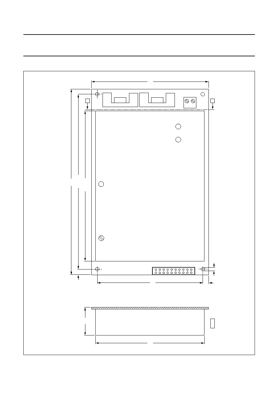
9
MECHANICAL SPECIFICA
TIONS
handbook, full pagewidth
160
152.86
130.4
43
MGU420
100
92.7
88.90
5.56
3.50
A
3.58
A
A - A
Fig.4 HTRM800 long range reader module.
Dimensions in mm.
2001 Oct 04
12
Philips Semiconductors
Product specification
HITAG long range reader module
hardware
HTRM800 family
10 APPLICATION INFORMATION
10.1
Metallic environment and interferences
The communication range is impaired by metallic
environment and electromagnetic interferences
(e.g. monitors and keyboards). Therefore, you should
keep a distance of at least one time the antenna diameter
to metallic surfaces or loops as well as to electromagnetic
interferences. If this is not possible, you have to take
preventive measures such as using ferrites or shielding for
transponder and antenna.
The HTRM800 is able to suppress up to two harmonic
electromagnetic disturbances.
10.2
Distance between two antennas
In order to be able to operate two systems side by side
without negative influence on communication ranges, you
must place the antennas at a minimum distance. To keep
this distance low, magnetic shielding must be realized.
This topic is handled in detail in application note
"Antenna
Design for the HITAG Long Range System".
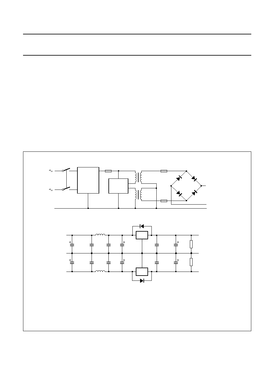
10.3
External power supply
Instead of a transformer type supply unit (see Fig.5),
a switching frequency power supply unit can be used
alternatively. The switching frequency must be in the
range from 165 to 210 kHz (overtemperature, load and
production).
handbook, full pagewidth
STANDARD
NET
FILTER
F1
F2
F3
A
B
C
D1
1N4001
D2
D4
D3
800 mA
(18 V)
800 mA
(18 V)
OPTIONAL
VOLTAGE
SELECTOR
MGU423
Fig.5 Transformer type power supply.
handbook, full pagewidth
7815
2200
µ
F
(40 V)
10
µ
F
(40 V)
10
µ
F
(40 V)
10
µ
F
(18 V)
10
µ
F
(18 V)
2200
µ
F
(40 V)
100
nF
100
nF
100
nF
100
nF
100
nF
1 k
1 k
100
nF
IN4001
IN4001
+
15 V
-
15 V
GND
C
MGU424
A
B
7915
72
µ
H 3A
72
µ
H 3A
F1 = depends on the type of transformer.
F2 = 800 mA delayed.
F3 = 800 mA delayed.
D1 = D2 = D3 = D4 = 4 x 1N4001.
2001 Oct 04
13
Philips Semiconductors
Product specification
HITAG long range reader module
hardware
HTRM800 family
10.4
Possible sources of errors by connecting the
HTRM800
The following error list should be checked if any error
(e.g. read or write distances that do not reach the specified
values) occurs:
·
Power supply cable not mounted correctly
·
Power supply voltage not in the specified range
·
Serial interface not connected correctly
·
Interference received by the antenna because of an
external noise source (e.g. monitor, keyboards); the
remedial measure is to remove the antenna from the
interfering area and use the command StartFFT
·
Connecting cables of the antenna changed by mistake
·
Antenna is mounted in metal environment; the remedial
measure is to mount a non-metal space keeper between
the antenna and the metal
·
Antenna is not designed following the antenna design
instructions
·
Inductance of the antenna is not in the specified range
·
Quality factor of the antenna is not in the specified
range.
10.5
Building HITAG long range antennas
10.5.1
B
ASICS
The exact way how to design a HITAG long range antenna
is described in application note
"Antenna Design for the
HITAG Long Range System".
The antenna is an important part of the HITAG long range
system. The antenna must provide energy and data
transmission between the reader module and transponder.
Therefore, you should be particularly careful when
implementing the antenna in order to achieve optimum
results.
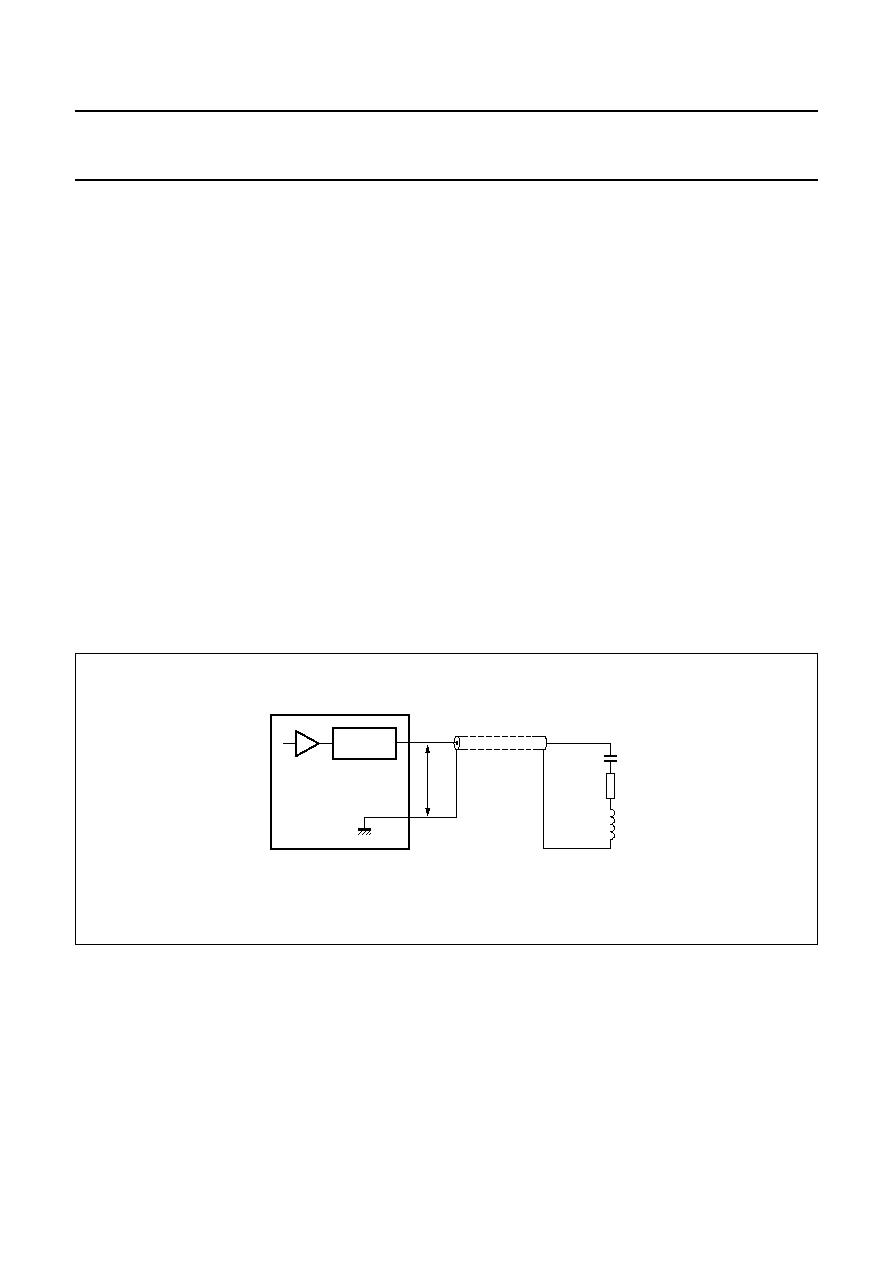
The equivalent circuit of the antenna is shown in Fig.6.
The requirements of the antenna coil are:
·
Quality factor: Q = 30 to 60
where
X
s
= effective series reactance
R
s
= effective series resistance
·
Inductance: L = 400 to 1200
µ
H.
Q
X
s
R
s
------
=
handbook, full pagewidth
VOLTAGE
LIMITER
coax cable
MGU421
antenna
Vo
C
Rs
Xs
HTRM800
Fig.6 Basics of the long range antenna.

2001 Oct 04
14
Philips Semiconductors
Product specification
HITAG long range reader module
hardware
HTRM800 family
10.5.2
R
ECOMMENDED ANTENNA CABLE AND LENGTH
The length of the antenna cable should be limited with five
meters. In case of longer cables a type with low
capacitance and resistance must be used. For standard
applications a 50
coaxial cable is recommended and a
75 or 95
coaxial cable for special applications.
10.5.3
T
UNING OF THE ANTENNA CURRENT
Potentiometer R72 (see Fig.2) is used to tune the current
driven through the antenna. The default setting is 200 mA.
It is not customary to change this value. However, if you
want to change the current for a special application, it
should be noted that V
o(peak)
< 10 V.
10.5.4
T
UNING OF THE ANTENNA PHASE
The signal from a transponder is delayed by the decay
time of the antenna. To achieve optimal performance this
signal and the digital signal processing unit of the reader
module must be synchronous. Thus it is necessary to store
a phase information called Bit Clock Delay (BCD), which is
a function of the quality factor and the inductance
(reactance) of the antenna.
The default setting is 7 which is suitable in most of the
cases. Apart from that, the user is able to change the BCD
value. The reader module includes a non volatile memory
(EEPROM) to store the bit clock delay. To load the BCD
value to the reader module the command SetBCD is used.
10.5.5
HITAG
ANTENNA TUNING DEVICE
Especially for the HITAG product line the HITAG antenna
tuning device HTOT840 was designed. This tuning device
can be used for tuning long range and proximity antennas.
10.5.6
A
NTENNA MALFUNCTION INDICATION
If the antenna is broken or badly detuned, the antenna
overload bit is set. This bit can be read by the host system
via the serial interface by using the command
ReadLRStatus.
10.5.7
A
DDITIONAL REMARKS
The following list is a summary about HITAG long range
antennas:
·
Philips lays high emphasis on the research of antenna
development
·
The choice of various antenna shapes (the electrical
parameters) is characteristic to 125 kHz systems
·
The knowledge is transferred to Philips customers, in
order to enable them to design and build antennas which
fit best for the particular applications (antenna training)
·
Solutions can be found for almost every environmental
scene (metal, periodic disturbers, special antenna
shapes, etc.).
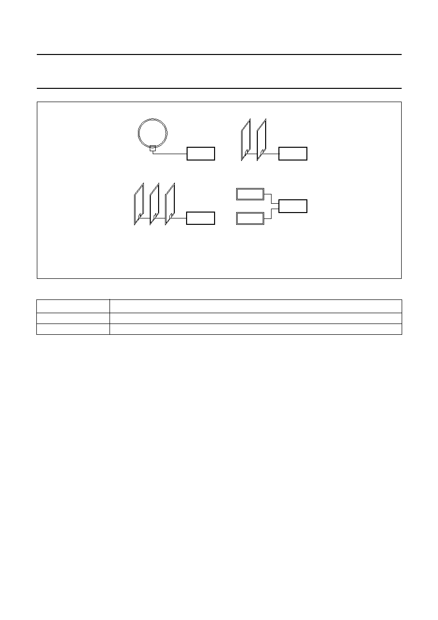
10.6
Antenna arrangements
Various arrangements are suitable for different
applications (see Fig.6):
·
The single loop antenna is used for standard
arrangements
·
The gate antenna is used for typical access control
applications such as access control during passing
through the gate
·
The double gate antenna is similar to the gate using two
rows
·
The antenna multiplex system is a cost efficient
application, because one reader module drives many
antennas and the number of multiplexed antennas is
only limited by timing restrictions.
By changing the arrangement of the antenna, the total
system performance and reliability can be significantly
improved. As an example: building gate antennas with
opposite magnetic orientation leads to a very reliable
system.
2001 Oct 04
15
Philips Semiconductors
Product specification
HITAG long range reader module
hardware
HTRM800 family
handbook, full pagewidth
HTRM800
HTRM800
antenna multiplex
MGU422
gate antenna
double gate multiplex
single loop antenna
HTRM800
HTRM800
Fig.6 Possible arrangements of antennas.
11 SURVEY OF REFERENCED DOCUMENTS
CATEGORY
TITLE
Data sheet
"HTCM400, HTRM440 Family, HTRM800 Family HITAG Interface Protocol Reader - Host"
Application note
"Antenna Design for the HITAG Long Range System"

2001 Oct 04
16
Philips Semiconductors
Product specification
HITAG long range reader module
hardware
HTRM800 family
12 DATA SHEET STATUS
Notes
1. Please consult the most recently issued data sheet before initiating or completing a design.
2. The product status of the device(s) described in this data sheet may have changed since this data sheet was
published. The latest information is available on the Interned at URL tap://www.semiconductors.philips.com.
DATA SHEET STATUS
(1)
PRODUCT
STATUS
(2)
DEFINITIONS
Objective data
Development
This data sheet contains data from the objective specification for product
development. Philips Semiconductors reserves the right to change the
specification in any manner without notice.
Preliminary data
Qualification
This data sheet contains data from the preliminary specification.
Supplementary data will be published at a later date. Philips
Semiconductors reserves the right to change the specification without
notice, in order to improve the design and supply the best possible
product.
Product data
Production
This data sheet contains data from the product specification. Philips
Semiconductors reserves the right to make changes at any time in order
to improve the design, manufacturing and supply. Changes will be
communicated according to the Customer Product/Process Change
Notification (CPCN) procedure SNW-SQ-650A.
13 DEFINITIONS
Short-form specification
The data in a short-form
specification is extracted from a full data sheet with the
same type number and title. For detailed information see
the relevant data sheet or data handbook.
Limiting values definition
Limiting values given are in
accordance with the Absolute Maximum Rating System
(IEC 60134). Stress above one or more of the limiting
values may cause permanent damage to the device.
These are stress ratings only and operation of the device
at these or at any other conditions above those given in the
Characteristics sections of the specification is not implied.
Exposure to limiting values for extended periods may
affect device reliability.
Application information
Applications that are
described herein for any of these products are for
illustrative purposes only. Philips Semiconductors make
no representation or warranty that such applications will be
suitable for the specified use without further testing or
modification.
14 DISCLAIMERS
Life support applications
These products are not
designed for use in life support appliances, devices, or
systems where malfunction of these products can
reasonably be expected to result in personal injury. Philips
Semiconductors customers using or selling these products
for use in such applications do so at their own risk and
agree to fully indemnify Philips Semiconductors for any
damages resulting from such application.
Right to make changes
Philips Semiconductors
reserves the right to make changes, without notice, in the
products, including circuits, standard cells, and/or
software, described or contained herein in order to
improve design and/or performance. Philips
Semiconductors assumes no responsibility or liability for
the use of any of these products, conveys no licence or title
under any patent, copyright, or mask work right to these
products, and makes no representations or warranties that
these products are free from patent, copyright, or mask
work right infringement, unless otherwise specified.

2001 Oct 04
17
Philips Semiconductors
Product specification
HITAG long range reader module
hardware
HTRM800 family
NOTES

2001 Oct 04
18
Philips Semiconductors
Product specification
HITAG long range reader module
hardware
HTRM800 family
NOTES

2001 Oct 04
19
Philips Semiconductors
Product specification
HITAG long range reader module
hardware
HTRM800 family
NOTES

© Koninklijke Philips Electronics N.V. 2001
SCA73
All rights are reserved. Reproduction in whole or in part is prohibited without the prior written consent of the copyright owner.
The information presented in this document does not form part of any quotation or contract, is believed to be accurate and reliable and may be changed
without notice. No liability will be accepted by the publisher for any consequence of its use. Publication thereof does not convey nor imply any license
under patent- or other industrial or intellectual property rights.
Philips Semiconductors a worldwide company
Contact information
For additional information please visit http://www.semiconductors.philips.com.
Fax: +31 40 27 24825
For sales offices addresses send e-mail to: sales.addresses@www.semiconductors.philips.com.
Printed in The Netherlands
613502/02/pp
20
Date of release:
2001 Oct 04
Document order number:
9397 750 08331
Document Outline
- 1 FEATURES
- 2 APPLICATIONS
- 3 GENERAL DESCRIPTION
- 4 ORDERING INFORMATION
- 5 BLOCK DIAGRAM
- 6 PINNING
- 6.1 ST1 connector
- 6.2 ST2 connector
- 7 FUNCTIONAL DESCRIPTION
- 7.1 System overview
- 7.2 Reader module software
- 7.3 Reader module hardware
- 7.4 Postal approval
- 7.5 Operating security
- 7.6 Security considerations
- 8 ELECTRICAL SPECIFICATIONS
- 9 MECHANICAL SPECIFICATIONS
- 10 APPLICATION INFORMATION
- 10.1 Metallic environment and interferences
- 10.2 Distance between two antennas
- 10.3 External power supply
- 10.4 Possible sources of errors by connecting the HTRM800
- 10.5 Building HITAG long range antennas
- 10.6 Antenna arrangements
- 11 SURVEY OF REFERENCED DOCUMENTS
- 12 DATA SHEET STATUS
- 13 DEFINITIONS
- 14 DISCLAIMERS