
SML-011 / 012 series
Light Emitting Diodes
1/3
Chip LEDs with reflectors
SML-011 / 012 series
The SML-011 / 012 series are ultra high luminance chip LEDs with reflectors by using AlGaInP die.
!
!
!
!
Features
1) Reflectors are used to achieve a high
luminance.
2) Two series : SML-011, SML-012
Three colors : red, orange and yellow
3) Rectangular and leadless (3
◊2mm).
4) Can be mounted by automatic mounting.
!
!
!
!
External dimensions (Units : mm)
3.0
2.0
1.6
2.3
0.5
0.3
1.6
Electrode
1.7
2
-
R0.3
Cathode mark
Through hole
1.3
+
0.2
-
0.1
Tolerances are
±
0.2 unless otherwise noted:
!
!
!
!
Selection guide
Emitting color
Lens
Transparent clear
Red
Orange
Yellow
SML-011VT
SML-012VT
SML-011DT
SML-012DT
SML-011YT
SML-012YT
!
!
!
!
Absolute maximum ratings (Ta=25
∞C)
Pulse width 1ms Duty 1 / 5
Parameter
Symbol
P
D
I
F
I
FP
V
R
Topr
Tstg
Limits
Unit
mW
mA
mA
V
∞
C
∞
C
4
-
40~
+
100
-
40~
+
100
78
30
60
Power dissipation
Forward current
Peak forward current
Reverse voltage
Operating temperature
Storage temperature

SML-011 / 012 series
Light Emitting Diodes
2/3
!
!
!
!
Electrical and optical characteristics (Ta=25
∞C)
Parameter
Forward voltage
Reverse
current
Type
SML-011
SML-012
VT
DT
YT
VT
DT
YT
Red
Orange
Yellow
Red
Orange
Yellow
2.0
Typ.
Color
2.0
2.0
2.0
2.0
2.0
2.6
Max.
20
I
F
(mA)
Max.
I
R
(
µ
A)
V
R
(V)
Cond.
Typ.
P
(nm)
I
F
(mA)
Cond.
Spectral line
half width
Typ.
(nm)
I
F
(mA)
Cond.
Cond.
V
F
(V)
Luminous intensity
Peak
wavelength
Min.
Typ. I
F
(mA)
Cond.
I
V
(mcd)
100
4
22.0
22.0
22.0
36.0
36.0
36.0
63.0
20
630
20
18
17
15
18
17
15
20
20
20
20
20
20
20
20
20
20
20
611
590
630
611
590
20
20
20
20
20
63.0
63.0
100
100
100
4
4
4
4
4
100
100
100
100
100
20
20
20
20
20
2.6
2.6
2.6
2.6
2.6
!
!
!
!
Directional pattern
ANGLE (
∞
)
RELATIVE LUMINOUS INTENSITY (%)
Fig.1 Directional pattern
0
50
100
50
100
0
10
10
20
20
30
40
50
60
70
80
90
30
40
50
60
70
80
90
!
!
!
!
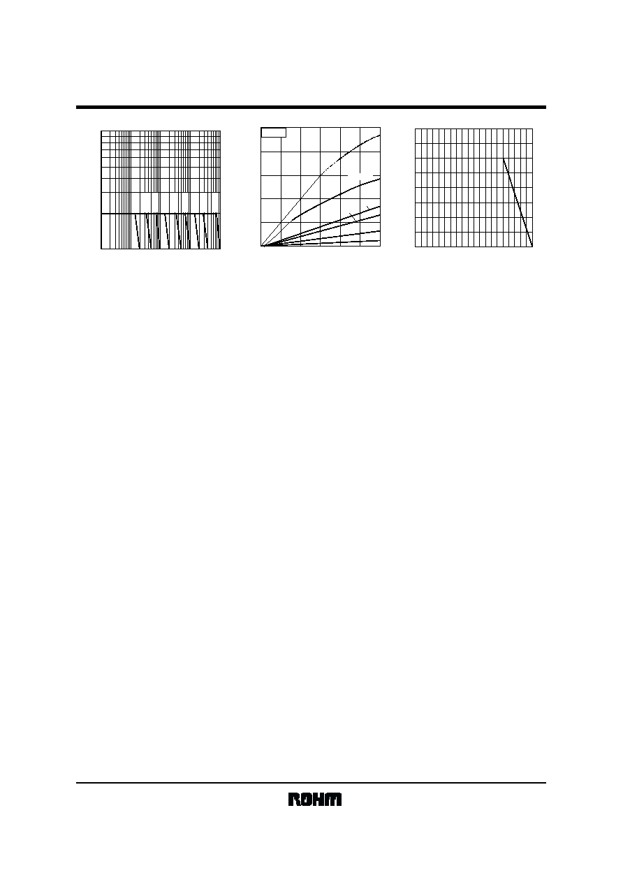
Electrical characteristic curves
10.0
1.0
1.5
1.0
2.0
2.5
3.0
100.0
FORWARD VOLTAGE : V
F
(V)
Fig.2 Forward current
vs. forward voltage
FORWARD CURRENT : I
F
(
mA
)
Ta
=
25
∞
C
1.4
1.2
1.0
0.8
0.6
0.4
40 50
-
30
-
20
-
10
20 30
0 10
60 70 80 90 100
1.6
RELATIVE LUMINOUS INTENSITY
I
F
=
20mA
Fig.3 Luminous intensity
vs. case temperature
CASE TEMPERATURE : T
C
(
∞
C)
2
1
0.5
0.2
0.1
0.05
0.02
0.01
0.5
1
2
5
10
20
50
100
5
FORWARD CURRENT : I
F
(
mA)
Fig.4 Luminous intensity
vs. forward current
RELATIVE LUMINOUS INTENSITY
Ta
=
25
∞
C
SML-011 / 012 series
Light Emitting Diodes
3/3
1
2
10
I
FP
Max. / I
F
Max.
PULSE DURATION : T
W
(
µ
s)
10
1
100
1000
10000
50kHz
20kHz
10kHz
5kHz
2kHz
1kHz
500Hz
200Hz
100Hz
Fig.5 Maximum tolerable peak current
vs. pulse duration
250
200
150
100
50
0
0
10
20
30
40
50
60
RELATIVE LUMINOUS INTENSITY
PEAK FORWARD CURRENT : (mA)
Fig.6 Luminous intensity
vs. forward current
f=1kHz
DF
=
50%
DC
10%
5%
15%
20%
20
10
0
0
10 20 30 40 50
70 80 90
60
100
30
40
AMBIENT TEMPERATURE : Ta
(
∞
C)
Fig.7 Dirating
MAXIMUM FORWARD CURRENT : (mA)