 | –≠–ª–µ–∫—Ç—Ä–æ–Ω–Ω—ã–π –∫–æ–º–ø–æ–Ω–µ–Ω—Ç: KS58006 | –°–∫–∞—á–∞—Ç—å:  PDF PDF  ZIP ZIP |

KS58006 TONE/PULSE DIALER WITH REDIAL
INTRODUCTION
The KS58006 is DTMF/PULSE switchable dialer with a 32-digit redial which
can be done using a slide switch. All necessary dual-tone frequencies are
derived from a 3.579545 MHz TV crystal or ceramic resonator providing very
high accuracy and stability. The required sinusoidal wave form for each in-
dividual tone is digitally synthesized on the chip. The generated wave form
has very low total harmonic distortion (7% max). A voltage reference is
generated on the chip which is stable over the operating voltage and tem-
perature range and regulates the single levels of the dual tone to meet telephone
industry specifications. CMOS technology is applied to this device, for very
low power requirements high noise immunity, and easy interface to a variety
of telephones requiring external components.
FEATURES
∑
Tone/Pulse switchable (slide switch)
∑
32-digit capacity for redial
∑
Automatic mix redialing ( last number dial ) of
PULSE
DTMF with multiple auto access pause
∑
PABX auto-pause for 3.5 sec.
∑
4 X 4 or ( 2 of 8 ) keyboard available
∑
Two key single tone operation
∑
Operating Voltage : 2.0 ~ 5.5V
∑
Numbers dialed manually after redial are cascadable
and stored as additional numbers for next redialing
∑
Uses inexpensive TV crystal or ceramic resonator
(3.579545MHz)
∑
Make/Break ratio (33.3 / 66.6) pin selectable
∑
Touch key hooking (604ms)
∑
Low standby current
∑
Improved EMI characteristic
∑
Improved redial memory quality
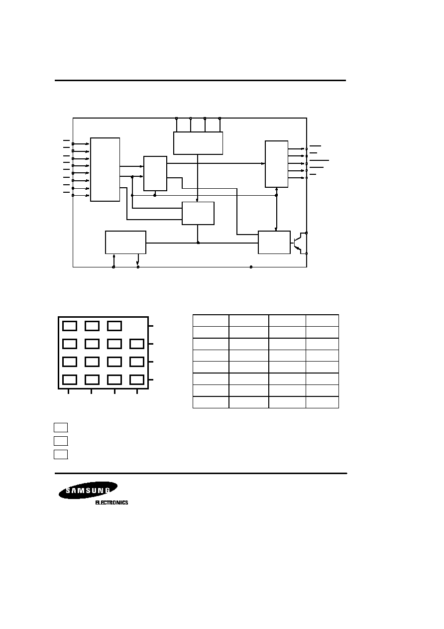
PIN CONFIGURATION
Fig. 1
Device
Package
Operating Temperature
KS58006N
18-DIP-300A
- 20
∞
C ~ + 70
∞
C
1
2
3
4
5
6
7
8
9
10
11
12
13
14
15
16
17
18
KA58006
R1
R2
R3
R4
HS
M/B
MDS
OSC IN
OSC OUT
C4
C3
C2
C1
DP
X'
TONE OUT
V
SS
V
DD
MUTE
18-DIP-300A
ORDERING INFORMATION
KS58006 TONE/PULSE DIALER WITH REDIAL
BLOCK DIAGRAM
Fig. 2
ARRANGEMENT OF KEYBOARD
TONE FREQUENCIES
C1 C2 C3 C4
* KEYBOARD DESCRIPTION
: HOOKING (604ms)
: PAUSE (3.5 second)
: REDIAL
KEYBOARD
LOGIC
RED IAL
MEMORY
32 DIGIT
INPUT LOGIC
CONTROL
LOGIC
OSC
DTMF
GENERATOR
OUPUT
LOGIC
R1
R2
R3
R4
C4
C3
C2
C1
MUTE
MDO
OSC IN
OSC OUT
X'
TONE OUT
V
SS
V
DD
MUTE
KIT
DP
HS
M/B MDS OPERATION
Input
Specified
Actual
% Error
R1
697
699.1
+ 0.31
R2
770
766.2
- 0.49
R3
852
847.4
- 0.54
R4
941
948.0
+ 0.74
C1
1209
1215.7
+ 0.57
C2
1336
1331.7
- 0.32
C3
1477
1471.9
- 0.35
1
2
3
4
5
6
HK
7
8
9
P
*
0
#
RD
R1
R2
R3
R4
HK
P
RD

KS58006 TONE/PULSE DIALER WITH REDIAL
PIN DESCRIPTION
Pin No
Symbol
Description
1- 4
15 -18
R1 - R4
C1 - C4
Keyboard (R1, R2, R3, R4, C1, C2, C3, C4)
These inputs can be interfaced to an XY matrix keyboard.
C1-C4 & R1-R4 are set to low at On Hook (HS = high). C1-C4 key inputs are set
to low and R1-R4 are set to high at OFF HOOK (HS = low) which enables the key-
input operation. The oscillator starts running when a keypress is detected. Scanning
signals are presented at both column and row inputs (TYP : 437Hz) until the
input key is released. Key inputs are compatible with standard 2-of-8 form or
single-contact keyboard. Debouncing is provided to avoid false entry (TYP : 4mS).
5
HS
Hook Switch
This input detects the state of the hook switch contack. "Off Hook"
corresponds to V
SS
condition. "On Hook" corresponds to V
DD
condition.
6
M/B
Make/Break Ratio
This input provides the selection of the Make/Break ratio (33.3: 66.6/40:60)
when M/B is connected to V
DD
/V
SS
.
Mode Select Input
Pulse/DTMF mode is selected as shown is the following table.
Initial Mode means the state after going Off Hook (HS
"V
SS
")
7
MDS
V
DD
Pulse
MDS
Input = V
SS
V
SS
Tone
N/A
8 - 9
OSC IN
OSC OUT
Oscillator Input/Output
These pins are provided to connect an external 3.58MHz crystal. Oscillator
starts (at Off Hook) and is sustained unitl pulse or DTMF signals are finished.
10 - 11
V
DD
, V
SS
Power
These are the power supply inputs. The device is designed to be operated on
2.0V to 5.5V
12
TONE OUT
DTMF Signal Output
When a valid keypress is detected in DTMF mode, appropriate low and high
group frequencies are generated which hybrid the Dual Tone Output.
Tone out is Off State in pulse mode.
X'MUTE Output
HS
X'MUTE Output
13
X'MUTE
V
DD
"ON"
Normally "OFF"
"ON" during pulse and DTMF dialing
(N channel open drain)
14
DP
Dial Pulse Out
DP : The normal output will be "ON" during break and "OFF" during make at
"OFF HOOK". The output will be "OFF" at "ON HOOK".
V
SS
MDS
INITAL
MODE
SWITCHING
ENTRY MODE
KS58006 TONE/PULSE DIALER WITH REDIAL
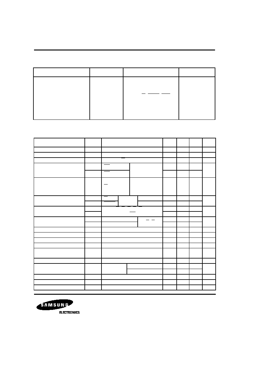
ABSOLUTE MAXIMUM RATINGS
ELECTRICAL CHARACTERISTICS
(V
SS
= 0V, V
DD
= 3.5V, f
X'TAL
= 3.579545MHz, Ta = 25
∞
C, unless otherwise noted)
Characteristic
Symbol
Value
Unit
Supply Voltage
Input Voltage
Output Voltage
Output Voltage
Tone Output Current
Power Dissipation
Operating Temperature
Storage Temperature
V
DD
V
I
V
O
V
O (DXM)
I
O (TONE)
P
D
T
OPR
T
STG
6.0
V
SS
- 0.3, V
DD
+ 0.3
V
SS
- 0.3, V
DD
+ 0.3
V
DD
(DP, X'MUTE, MUTE)
50
500
- 20 ~ + 70
- 40 ~ + 125
V
V
V
V
mA
mW
∞
C
∞
C
Characteristic
Symbol
Test Conditions
Min
Typ
Max
Unit
Operating Voltage Range
V
DD
2.0
5.5
V
Memory Retention Voltage
V
MR
1.0
V
Memory Retention Current
I
MR
HS = V
DD
= 1.0V
0.05
0.1
µ
A
I
DD (PULSE)
MDS = V
DD
0.1
0.3
I
DD (TONE)
MDS = V
SS
0.4
0.7
10
50
µ
A
I
OL1
DP,
V
DD
= 3.5V
1.7
5.0
I
OL2
X'MUTE
V
DD
= 2.5V
0.5
1.5
V
IH
R1-R4, C1-C3, HS, M/B
0.8V
DD
V
DD
V
IL
MDS
V
SS
0.2V
DD
I
L1
V
DD
= 3.5V, V
IN
= 0V
50
I
L2
V
DD
= 2.5V, V
IN
= 0V
30
Valid Key Entry Time
t
KD
23
mS
Key Release Time
t
KR
5
mS
Tone Duration
t
TD
110
mS
Tone Interdigit Pause Time
t
TIDP
110
mS
Column and Row
Scanning Frequency
437
Hz
Auto Access Pause Time
t
AP
3.5
sec
V
DD
= 2.5V, R
L
= 5K
-14.0
-12.0
V
DD
= 3.5V, R
L
= 5K
-14.0
-12.0
Ratio of Column to Row Tone
dB
CR
V
DD
= 3.5V
1.0
2.0
3.0
dB
Distortion
THD
V
DD
= 3.5V
7
%
Tone Output Delay Time
t
D(TONE)
1.5
mS
Operating Current
Standby Current
Output Current
Input Voltage
Input Current
Tone Output
I
SB
f
CR
V
O(TONE)
One key selected
HS=V
SS
, All outputs
Unloaded
HS = V
SS
No key selected.
All outputs
unloaded
V
OL
= 0.4V
R1-R4
mA
mA
V
µ
A
dBV
ROW TONE
ONLY
KS58006 TONE/PULSE DIALER WITH REDIAL
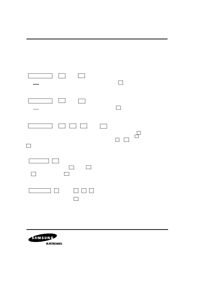
APPLICATION INFORMATION
KEYBOARD OPERATION
1. SINGLE MODE OPERATION
Pulse Mode Operation
. . .
The pulse mode is defined by the initial mode after going off Hook and latched at key entry. This is the condition
under MDS = V
DD
.
Tone Mode Operation
. . .
The tone mode is defined by the initial mode after going off Hook and latched at key entry. This is the condition
under MDS = V
SS
.
Manual Dialing with Automatic Access Pause
. . .
Multiple Pause key entries can be accepted and stored in the redial memory, each as a digit. Each key provides
3.5 seconds pause time, but the P key entry as the first digit after going Off Hook is ignored. The key can also
be used as a pause key in the pulse mode. Pause (2) can be cancelled with the or key during pause time
in redialing.
= Any numeric key.
Redialing
Up to 32 digits can be dialed with the key. The key is disabled while pulse or DTMF signals are transmitted.
When more than 32 digits are stored, redial is also inhibited.
The key can be used as the key in the pulse mode.
Inhibiting Redial
. . .
Redial can be inhibited by depressing the key twice after DTMF or pulse signals are transmitted.
D1
Off Hook
D1
Dn
Off Hook
D1
Dn
D1
Off Hook
D
P
D1
Dn
P
*
P
RD
D
Off Hook
RD
RD
RD
#
RD
Off Hook
D1
Dn
RD
RD
RD
KS58006 TONE/PULSE DIALER WITH REDIAL
2. PULSE/TONE SWITCHABLE OPERATION
Mode Switching by MDS Input
. . . . . .
Pulse Mode DTMF Mode
The pulse mode is initially defined MDS = V
DD
, mode switching to the DTMF mode can be accepted by MDS = V
SS
,
the DTMF mode will be set up after the pulse mode is finished. In this mode, digits Dn + 1 ... Dn + m are transmitted
from Tone Out as DTMF signals by depressing the corresponding keys.
If no P key is contained serially before or after mode switching, the following condition is obtained.
. . . . . .
Pulse Mode DTMF Mode
(Dn+1
Pause)
If digit is depressed after the pulse mode is finished, the DTMF mode will be set up after last the pulse signal
( ) is generated. In this mode,digits ... are transmitted from Tone Out as DTMF signals by depress-
ing the corresponding keys. If digit is depressed during dialing pulse signals. What happens? When the DTMF
mode is set, the Hold State will be set after last pulse signal Dn is finished. MDO
will flash to indicate this Hold
State, ... are stored in redial memory as DTMF DATA and not transmitted from Tone Out. When it is
ready to transmit DTMF data in redial memory, the or key is depressed to reset this Hold State and
... data are serially transmitted.
Off Hook
D1
Dn
P
Switching MDS to V
SS
Dn+1
DN+m
Off Hook
D1
Dn
Switching MDS to V
SS
Dn+1
Dn+m
Dn+1
Dn
Dn+1
Dn+m
Dn+
1
Dn+1
Dn+m
Dn+1
Dn+m
RD
P
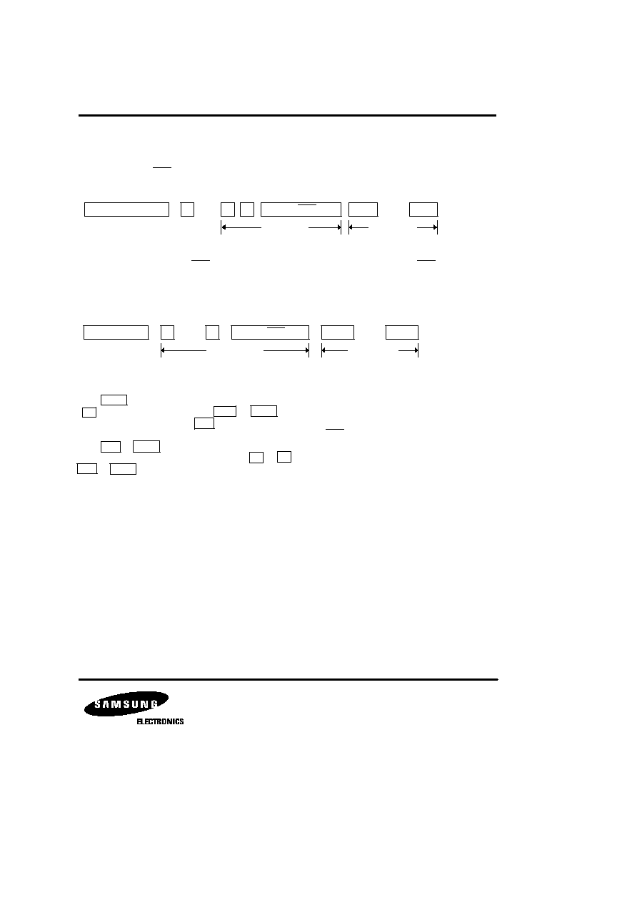
KS58006 TONE/PULSE DIALER WITH REDIAL
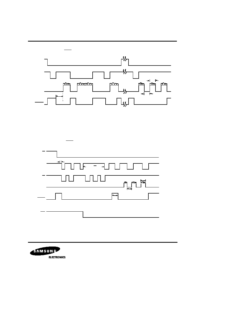
TONE MODE TIMING (MDS = V
SS
)
Fig. 3
PULSE MODE TIMING (MDS = V
DD
)
Fig. 4
KEY INPUT
4
3
.
RD
TONE
4
3
.
X'MUTE
t
TIDP
t
T IDP
t
TID P
HS
KEY INPUT
DP
TONE OUT
MDS
D
2
3
P
Swi tching MS = V
S S
*
2
1
8
t
PA
t
TIDP
t
T D
X'MUTE

KS58006 TONE/PULSE DIALER WITH REDIAL
TIMING DIAGRAM
(for Switching Mode Operation by MDS Input)
t
PA
: 3.5 sec
Fig. 5
HS
KEY INPUT
DP
TONE OUT
MDS
D
2
3
P
Switching MS = V
S S
*
2
1
8
t
PA
t
TIDP
t
T D
X'MUTE