 | –≠–ª–µ–∫—Ç—Ä–æ–Ω–Ω—ã–π –∫–æ–º–ø–æ–Ω–µ–Ω—Ç: SDK03M | –°–∫–∞—á–∞—Ç—å:  PDF PDF  ZIP ZIP |
36
SDK03M
2-Phase Stepper Motor Unipolar Driver ICs
SDK03M
s
Electrical Characteristics
s
Absolute Maximum Ratings
Parameter
Symbol
Ratings
Units
min
typ
max
Control supply current
I
S
5
7.5
mA
Condition
V
S
=44V
Control supply voltage
V
S
10
24
44
V
FET Drain-Source
V
DSS
100
V
voltage
Condition
V
S
=44V, I
DSS
=250
µ
A
FET ON voltage
V
DS
0.85
V
Condition
I
D
=1A, V
S
=14V
FET drain leakage current
I
DSS
4
mA
Condition
V
DSS
=100V, V
S
=44V
FET diode forward
V
SD
1.2
V
voltage
Condition
I
D
=1A
I
IH
40
µ
A
TTL input current
Condition
V
IH
=2.4V, V
S
=44V
I
IL
-
0.8
mA
Condition
V
IL
=0.4V, V
S
=44V
V
IH
2
TTL input voltage
Condition
I
D
=1A
V
(Active High)
V
IL
0.8
Condition
V
DSS
=100V
V
IH
2
TTL input voltage
Condition
V
DSS
=100V
V
(Active Low)
V
IL
0.8
Condition
I
D
=1A
T
r
0.5
Condition
V
S
=24V, I
D
=0.8A
Switching time
T
stg
0.7
µ
s
Condition
V
S
=24V, I
D
=0.8A
T
f
0.1
Condition
V
S
=24V, I
D
=0.8A
Parameter
Symbol
Ratings
Units
Motor supply voltage
V
CC
46
V
FET Drain-Source voltage
V
DSS
100
V
Control supply voltage
V
S
46
V
TTL input voltage
V
IN
7
V
Reference voltage
V
REF
2
V
Output current
I
O
1
A
Power dissipation
P
D
2.5 (Without Heatsink)
W
Channel temperature
T
ch
+150
∞
C
Storage temperature
T
stg
-
40 to +150
∞
C
2-Phase/1-2 Phase Excitation
DC characteristics
AC characteristics

37
SDK03M
SDK03M
2-Phase Stepper Motor Unipolar Driver ICs (2-Phase/1-2 Phase Excitation)
s
Internal Block Diagram
s
Diagram of Standard External Circuit (Recommended Circuit Constants)
Excitation input
Active H
Active L
Pin 1
OUT
1
OUT
2
Pin 16
Pin 8
OUT
2
OUT
1
Pin 9
8
Reg.
2
3
12
1
6
10
5
7
+
≠
+
≠
15
13
4
16
9
IN
1
IN
2
V
S
14
11
NC
NC
R
S
R
S
R
S
GND
GND
REF
T
D
Active High
Active Low
+
V
CC
(46V max)
Motor coil
Phase A
Motor coil
Phase B
Motor coil
Phase A
Motor coil
Phase B
V
b
(5V)
1
16
8
9
7
6
5
IN
1
IN
2
12
10
15
13
3
C
3
r
5
R
S
4
C
1
C
2
r
2
r
6
C
4
R
S
OUT
1
OUT
2
V
S
GND
R
S
REF
T
D
IN
1
IN
2
2
r
3
r
1
r
4
2
SDK03M
Phase A
12
10
4
IN
1
IN
2
IN
1
IN
2
6
5
V
S
OUT
2
OUT
1
REF
R
S
GND
T
D
SDK03M
Phase B
7
1
16
8
9
3
13
15
Active
High
Active
High
+
V
CC
(46V max)
V
b
(5V)
1
16
8
9
7
6
5
IN
1
IN
2
12
10
15
13
3
C
3
r
5
R
S
4
C
1
C
2
r
2
r
6
C
4
R
S
OUT
2
OUT
1
V
S
GND
R
S
REF
T
D
IN
1
IN
2
2
r
3
r
1
r
4
2
SDK03M
Phase A
12
10
4
IN
1
IN
2
IN
1
IN
2
6
5
V
S
OUT
1
OUT
2
REF
R
S
GND
T
D
SDK03M
Phase B
7
1
16
8
9
3
13
15
Active
Low
Active
Low
1, 8, 9, 16pin Description of pins
Excitation signal time chart
2-phase excitation
Phase
clock
0
1
2
3
0
1
Phase A
IN
1
H
L
L
H
H
L
IN
2
L
H
H
L
L
H
Phase B
IN
1
H
H
L
L
H
H
IN
2
L
L
H
H
L
L
1-2-phase excitation
Phase
clock
0 1 2 3 4 5 6 7 0 1 2 3
Phase A
IN
1
H H L L L L L H H H L L
IN
2
L L L H H H L L L L L H
Phase B
IN
1
L H H H L L L L L H H H
IN
2
L L L L L H H H L L L L
Excitation signal time chart
2-phase excitation
Phase
clock
0
1
2
3
0
1
Phase A
IN
1
L
H
H
L
L
H
IN
2
H
L
L
H
H
L
Phase B
IN
1
L
L
H
H
L
L
IN
2
H
H
L
L
H
H
1-2-phase excitation
Phase
clock
0 1 2 3 4 5 6 7 0 1 2 3
Phase A
IN
1
L L H H H H H L L L H H
IN
2
H H H L L L H H H H H L
Phase B
IN
1
H L L L H H H H H L L L
IN
2
H H H H H L L L H H H H
r
1
:
510
r
2
:
100
(VR)
r
3
:
47k
r
4
:
47k
r
5
:
2.4k
r
6
:
2.4k
C
1 :
470pF
C
2 :
470pF
C
3 :
2200pF
C
4 :
2200pF
R
S
:
1.8
typ
r
1
:
510
r
2
:
100
(VR)
r
3
:
47k
r
4
:
47k
r
5
:
2.4k
r
6
:
2.4k
C
1 :
470pF
C
2 :
470pF
C
3 :
2200pF
C
4 :
2200pF
R
S
:
1.8
typ
(1 to 2W)
(1 to 2W)
38
SDK03M
SDK03M
2-Phase Stepper Motor Unipolar Driver ICs (2-Phase/1-2 Phase Excitation)
s
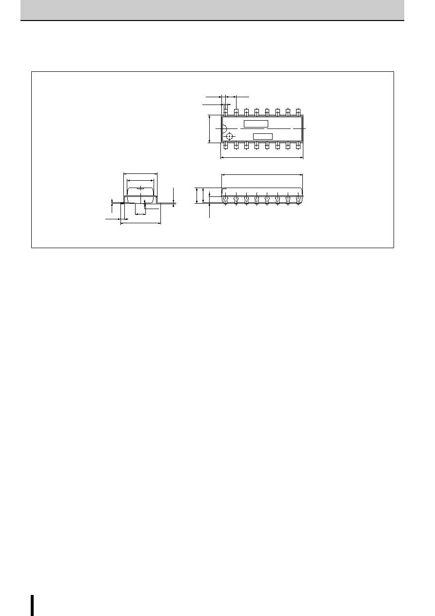
External Dimensions
(Unit: mm)
Part No.
Lot No.
2.54
±
0.25
0.75
+0.15
≠0.05
0.89
±
0.15
16
6.8
max.
20.0
max.
19.56
±
0.2
9
8
1
4.0
max.
3.6
±
0.2
1.4
±
0.2
0.3
+0.15 ≠
0.05
8.0
±
0.5
6.3
±
0.2
3.0
±
0.2
0~0.1
1.0
±
0.3
9.8
±
0.3
0.25
39
SDK03M
SDK03M
2-Phase Stepper Motor Unipolar Driver ICs (2-Phase/1-2 Phase Excitation)
R
S
C
3
r
2
r
1
r
6
r
5
V
b
(5
V
)
10
3
13 15
R
S
C
3
r
2
r
1
r
6
r
5
V
b
(5
V
)
10
3
r
X
T
r
Power down
signal
13 15
s
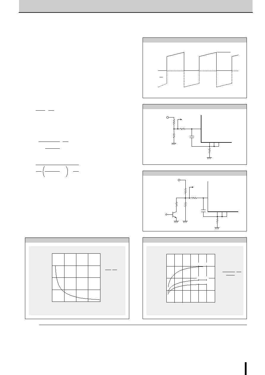
Determining the Output Current
Fig. 1 shows the waveform of the output current (motor coil cur-
rent). The method of determining the peak value of the output
current (I
O
) based on this waveform is shown below.
(Parameters for determining the output current I
O
)
V
b
: Reference supply voltage
r
1
,r
2
: Voltage-divider resistors for the reference supply voltage
R
S
: Current sense resistor
(1) Normal rotation mode
I
O
is determined as follows when current flows at the maximum
level during motor rotation. (See Fig.2.)
(2) Power down mode
The circuit in Fig.3 (r
x
and T
r
) is added in order to decrease the
coil current. I
O
is then determined as follows.
Equation (2) can be modified to obtain equation to determine r
x
.
Fig. 4 and 5 show the graphs of equations (1) and (2) respec-
tively.
Fig. 2 Normal mode
0
Phase A
Phase A
I
O
Fig. 1 Waveform of coil current (Phase A excitation ON)
Fig. 3 Power down mode
4
3
2
1
0
0
1
2
3
4
Current sense resistor R
S
(
)
Output current I
O
(A)
I
O
=
r
1
+r
2
R
S
r
1
=510
r
2
=100
r
x
=
V
b
=5V
r
2
∑
V
b
Fig. 4 Output current I
O
vs. Current sense resistor R
S
Fig. 5 Output current I
OPD
vs. Variable current sense resistor r
x
2.0
1.5
1.0
0.5
00
200
400
600
800
Variable current sense resistor r
X
(
)
Output current I
OPD
(A)
1000
1200
R
S
=0.5
R
S
=0.8
R
S
=1
I
OPD
=
1+ R
S
r
1
=510
r
2
=100
V
b
=5V
1
∑
V
b
r
1
(r
2+
r
X
)
r
2 ∑
r
X
Application Notes
r
X
=
1
V
b
R
s
∑
I
OPD
1
r
1
-
1
-
1
r
2
(NOTE)
Ringing noise is produced in the current sense resistor R
S
when
the MOSFET is switched ON and OFF by chopping. This noise
is also generated in feedback signals from R
S
which may there-
fore cause the comparator to malfunction. To prevent chopping
malfunctions, r
5
(r
6
) and C
3
(C
4
) are added to act as a noise filter.
However, when the values of these constants are increased,
the response from R
S
to the comparator becomes slow. Hence
the value of the output current I
O
is somewhat higher than the
calculated value.
................................................................ (1)
I
O
∑
r
2
r
1
+r
2
V
b
R
S
......................................................... (2)
I
OPD
∑
1
r
1
(r
2
+r
X
)
r
2
∑
r
X
V
b
R
S
1+

40
SDK03M
SDK03M
2-Phase Stepper Motor Unipolar Driver ICs (2-Phase/1-2 Phase Excitation)
60
50
40
30
20
10
0
0
2
4
6
8
10 12
14
16
15
20
25
30
35
40
Motor coil resistance R
m
(
)
ON time T
ON
( s)
V
CC
=2
4V
V
CC
=36V
Chopping frequency f (kHz)
T
OFF
=12 s
R
S
=1
L
m
=1~3ms
R
m
= =
r
3
C
1
r
4
C
2
47k
500pF
µ
µ
Fig. 6 Chopper frequency vs. Motor coil resistance
s
Determining the chopper frequency
Determining T
OFF
SDK03M is self-excited choppers. The chopping OFF time T
OFF
is fixed by r
3
/C
1
and r
4
/C
2
connected to terminal T
d
.
T
OFF
can be calculated using the following formula:
The circuit constants and the T
OFF
value shown below are rec-
ommended.
T
OFF
= 12
µ
s at r
3
=47k
, C
1
=500pF, V
b
=5V
s
Chopper frequency vs. Supply voltage
s
Chopper frequency vs. Output current
0
f (kHz)
V
CC
(V)
50
40
30
20
10
0
10
20
30
40
50
Motor : 23LM-C202
I
O
= 0.8A at V
CC
=24V
R
S
=1
0
f (kHz)
I
O
(A)
50
40
30
20
10
0
0.2
0.4
0.6
0.8
1.0
Motor : 23LM-C202
V
CC
=24V
R
S
=1
T
OFF
-
r
3
∑
C
1 n
(1
-
=
-
r
4
∑
C
2
n
(1
-
)
r
r
2
V
b
2
V
b
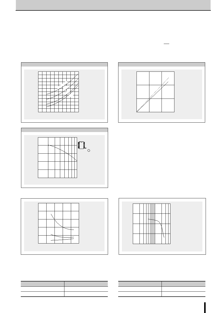
41
SDK03M
SDK03M
2-Phase Stepper Motor Unipolar Driver ICs (2-Phase/1-2 Phase Excitation)
s
Supply Voltage V
CC
vs. Supply Current I
CC
s
Torque Characteristics
0
Supply current I
CC
(mA)
Supply voltage V
CC
(V)
500
400
300
200
100
0
10
20
30
40
50
Motor : 23LM-C202
1-phase excitation
Holding mode
I
O
: Output current
I
O
=1A
0.4A
0.2A
100
Pull-out torque (kg-cm)
Response frequency (pps)
2.0
1.5
1.0
0.5
0
5K
1K
500
Motor : PX244-02
Output current I
O
=0.6A
Motor supply voltage V
CC
=24V
2-phase excitation
1.2
1
0.8
0.6
0.4
0.2
0
0
0.2
0.4
0.6
0.8
1.0
Heat dissipation per phase P
H
(W)
Output current I
O
(A)
36V
24V
15V
V
CC
=44V
Motor : 23LM-C202
Holding mode
Fig. 7 Heat dissipation per phase P
H
vs. Output current I
O
T
j
1
0
2
3
T
C
Glass epoxy board
(mounted on level surface)
(95
◊
69
◊
1.2mm)
Natural cooling
150
100
50
0
Total power (W)
T
j
≠
a
T
C
≠
a
(
∞
C)
50
40
30
20
10
0
200
500
1K
Case temperature rise
T
C
≠
a
(
∞
C)
Response frequency (pps)
T
C
( 9 pin)
Natural cooling
Glass epoxy board
(mounted on level surface)
(95
◊
69
◊
1.2mm)
Motor : PH265-01B
Motor current I
O
=0.8A
T
a
=25
∞
C
V
CC
=24V, V
S
=24V
2-phase excitation
Thermal characteristics
Fig. 8 Temperature rise
Active Low
Input
Corresponding output
IN
1
(pin6)
OUT
1
(pin8, 9)
IN
2
(pin5)
OUT
2
(pin1, 16)
Active High
Input
Corresponding output
IN
1
(pin6)
OUT
1
(pin1, 16)
IN
2
(pin5)
OUT
2
(pin8, 9)
s
Note
The excitation input signals of the SDK03M can be used as either Active High or Active Low. Note, However, that the corresponding
output (OUT) changes depending on the input (IN).
s
Thermal Design
An outline of the method for computing heat dissipation is shown below.
(1) Obtain the value of P
H
that corresponds to the motor coil current
I
O
from Fig. 7 "Heat dissipation per phase P
H
vs. Output current
I
O
."
(2) The power dissipation Pdiss is obtained using the following formula.
2-phase excitation: P
diss
P
H
+0.0075
◊
V
S
(W)
1-2 phase excitation: P
diss
P
H
+0.0075
◊
V
S
(W)
(3) Obtain the temperature rise that corresponds to the calcu-
lated value of P
diss
from Fig. 8 "Temperature rise."
3
4