 | ÐлекÑÑоннÑй компоненÑ: SH1211 | СкаÑаÑÑ:  PDF PDF  ZIP ZIP |
SH1211 MouseCoder® data sheet
SH1211 MouseCoder®
Ergonomic Mouse
PS/2 and RS232 Encoder
Semtech, the Semtech logo, MouseCoder, and
HulaPoint are marks of Semtech Corporation.
Force Sensing Resistor and FSR are marks of
Interlink Electronics, Inc. MicroPoint is a mark of
Varatouch Technology, Inc. All other marks belong
to their respective owners.
Copyright ©1995-2003 Semtech Corporation
SH1211 data sheet v1.10 (2003-07)
www.semtech.com
1
HID & SYSTEM MANAGEMENT PRODUCTS, MOUSECODER® FAMILY
DESCRIPTION
FEATURES
· Embedded HulaPointsTM
· Industrial panels
· Joystick applications
· Industrial keyboards
· Instrumentation
· Gaming
· Works with a Hall-effect sensor
· Works with a resistive analog
joystick sensor
· Works with a switch joystick sensor
· Works with an FSR sensor
· Works with a Varatouch
MicroPointTM sensor
· Available in a small 32-pin plastic
LQFP package
· Advanced motion-control algorithm
for accurate cursor control
· Low power consumption in a
3.3 to 5.5 volt operating range
· Compatible with standard two-
button, three-button, and wheel
mice
· RS232 or PS/2 host interface
The SH1211 MouseCoder® is an
easy-to-use single-chip multi-
mouse encoder with an advanced
motion algorithm for accurate
cursor control. The SH1211 offers
low power consumption in a small-
footprint package, and connects to
a host serial or a PS/2 mouse port.
The SH1211 is designed for use
with a Fujitsu Takamisawa
FID-828 Hall-effect sensor
(HulaPointTM), a resistive analog
joystick sensor (like the CTS 252),
a switch joystick sensor, an FSR
sensor, or a Varatouch
MicroPointTM sensor, as well as
others.
The SH1211 provides an external
port for hot-plug connection of a
PS/2 mouse, including one with
wheel function.
SH1211 serial communication is
unidirectional at a fixed speed of
1200 Baud. PS/2 communication
is bidirectional at 10 Kbps. The
SH1211 is a CMOS device
operating at 4 MHz. It can return
mouse reports at the rate of 100
per second. The SH1211 is
compatible with the standard two-
button mouse protocol, the
standard three-button mouse
protocol, and standard wheel
mouse protocols. It implements all
commands from and to the system,
as defined in the IBM PS/2 mouse
communication protocol.
The SH1211's low power
consumption makes it ideal for
battery operated systems.
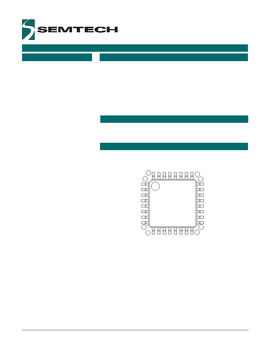
1
8
9
32
25
24
16
17
SEN00
SEN01
SEN02
SEN03
VREF
_RESET
VSS2
VDD
SEN14
SEN13
SEN12
SENSEL2
SEN11
MDAT/RTS
SENSEL1
EMCLK
SEN15
INTSEL
TxD
SCLK
SEN04
SEN05
SEN06
SEN07
SEN10
SEN09
EMDA
T
MCLK
SEN08
VSS
_OSCOUT
OSCIN
SH1211-FG
LQFP
APPLICATIONS
PIN ASSIGNMENTS
PRELIMINARY
ORDERING CODE
Copyright ©1995-2003 Semtech Corporation
SH1211 data sheet v1.10 (2003-07)
www.semtech.com
2
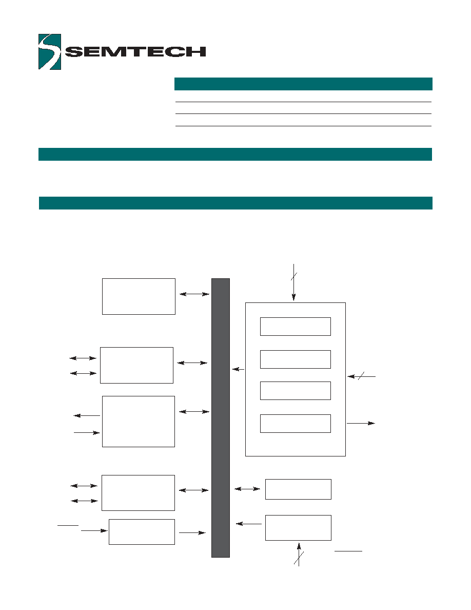
The SH1211 consists functionally of five major sections (see block diagram below). These are the Sensor Interface,
the 16-bit Timer, the Oscillator Circuit, the PS/2 Communication Port and the RS232 Communication Port. All
sections communicate with each other and operate concurrently.
BLOCK DIAGRAM
Data Buffer
Host PS/2
Communication
Port
External PS/2
Port
MCLK
MDAT
EMCLK
EMDAT
Sensor Interface
Oscillator Circuit
Power-on Reset
Switch Interface
X Input
Y Input
Control
OSCIN-OSCOUT
16-bit Timer
2
Sensor Power
Strobe
Analog Signal Input
4
Left, Middle/Up,
Right, & Down
Buttons
Host Serial
Communication
Port
TxD
RTS
RESET
FUNCTIONAL DESCRIPTION
SH1211-FG
LQFP 32-pin, 0.8 mm pitch, T
A
= -20°C to +85°C
EVK-SH1211
Evaluation kit

Copyright ©1995-2003 Semtech Corporation
SH1211 data sheet v1.10 (2003-07)
www.semtech.com
3
SENSOR CONFIGURATIONS
MOUSE EMULATION
The SH1211 emulates either a
standard 3-button mouse or a
standard wheel mouse. The state
of the button configuration pin
(BCONF, pin 20) determines which
mouse type is emulated. The pin
left floating specifies 3-button
mode, the pin tied to ground
specifies wheel mode.
In 3-button mode, the left, right and
middle buttons are implemented.
In wheel mode, the left, right, up,
and down buttons are
implemented; pressing up and
down buttons together emulates a
middle-button press.
POWER CONSUMPTION
The SH1211 typically consumes
less than 3 mA in standby for
HulaPointTM or analog joystick
sensors and less than 1 µA for
other sensors.
EXTERNAL PS/2 PORT
The SH1211 provides an external
PS/2 mouse port. Data from this
port is seamlessly merged with
data from the embedded sensor.
External mice, including those with
a mouse wheel, can be hot-plug
connected.
The SH1211 has built-in support applicable to many sensors, including the
following:
HulaPointTM Fujitsu Takamisawa FID-828 Hall-effect sensor
Analog joystick sensor such as the CTS 252
Switch joystick sensor
FSRTM sensor (Force Sensing ResistorTM, Interlink Electronics)
Varatouch MicroPointTM sensor
The states of the sensor select pins 18 and 21 (SENSEL1, SENSEL2)
indicate which sensor is being used.
The name, definition and use of the 16 sensor pins (SEN00-SEN15: pins 1-
4, 29-32, 15, 16, 20, 22-25) vary depending on which sensor is being used.
Refer to the schematics and pin definitions in this data sheet for specifics.
HOST INTERFACE
The SH1211 communicates with
the host system using either PS/2
or serial. The state of the interface
select pin (INTSEL, pin 26)
determines which interface is used.
If the pin is tied to ground, PS/2 is
used; if it is tied to power (Vcc),
serial is used.
PINS FOR HULAPOINTTM & ANALOG JOYSTICK SENSOR CIRCUITS
Copyright ©1995-2003 Semtech Corporation
SH1211 data sheet v1.10 (2003-07)
www.semtech.com
4
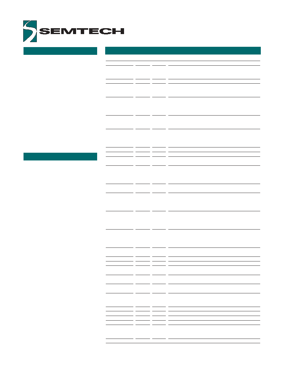
Pin Numbers
Mnemonic
Pin
Type
Name and Function
Power
V
DD
8
P
Power supply: +5V
V
SS
2, V
SS
7, 11
P
Ground
Reset
_RESET
6
I
Reset: apply 0V for orderly start-up
Oscillator
OSCIN
9
I
Oscillator input: external clock input or one side of the
ceramic resonator with built-in load capacitors
_OSCOUT
10
O
Oscillator output: open for external clock input or one
side of the ceramic resonator with built-in load
capacitors
Host
INTSEL
26
I
Host interface select: tie to ground for PS/2 host, tie to
power (V
CC
) for serial host
MCLK
13
I/O (nd) Host PS/2 clock
MDAT/RTS
19
I/O (nd) Host PS/2 data / serial ready-to-send
TxD
27
O
Serial transmit to host: idle high; in serial mode,
connect to host RxD; in PS/2 mode, leave floating
External PS/2
EMCLK
17
I/O (nd) External mouse clock: PS/2 clock signal from external
mouse
EMDAT
14
I/O (nd) External mouse data: PS/2 data signal from external
mouse
Select
SENSEL1-2
18, 21
I
Sensor select; for HulapointTMor analog joystick, leave
both floating
Reference
VREF
5
AI
Reference voltage for built-in A/D: for HulaPoint sensor,
connect to SPWR0
Sensor
SEN00-3
1-4
I/O
Switched power drivers; connect together
/SWPWR0-3
SEN04-5
29, 30
I/O
Switched power driver; connect to SWPWR0
/SWPWR4-5
SEN06/YAD
31
AI
Y-axis analog to digital converter input
SEN07/XAD
32
AI
X-axis analog to digital converter input
SEN08/_XYSWP 12
I
Leave floating for default X, Y axes; connect to ground
to swap X and Y axes
SEN09/_XINV
15
I
Leave floating for default X direction; connect to ground
for reversed X direction
SEN10/_YINV
16
I
Leave floating for default Y direction; connect to ground
for reversed Y direction
SEN11/BCONF
20
I
Button configuration: leave floating for standard
3-button mouse mode, tie to ground for
up/down/wheel-mouse mode
SEN12/_DB
22
I/O (nd) Down button: active low, strobed sampling
SEN13/_LB
23
I/O (nd) Left button: active low, strobed sampling
SEN14/_MB/_UB 24
I/O (nd) Middle button: active low, strobed sampling
SEN15/_RB
25
I/O (nd) Right button: active low, strobed sampling
Reserved
RSVD
28
Leave floating
An underscore before a pin
mnemonic denotes an active low
signal.
Pin types legend:
P = power
AI = analog input
I = input
O = output
I/O = input or output
I/O (nd) = input or output with
N-channel open drain driver
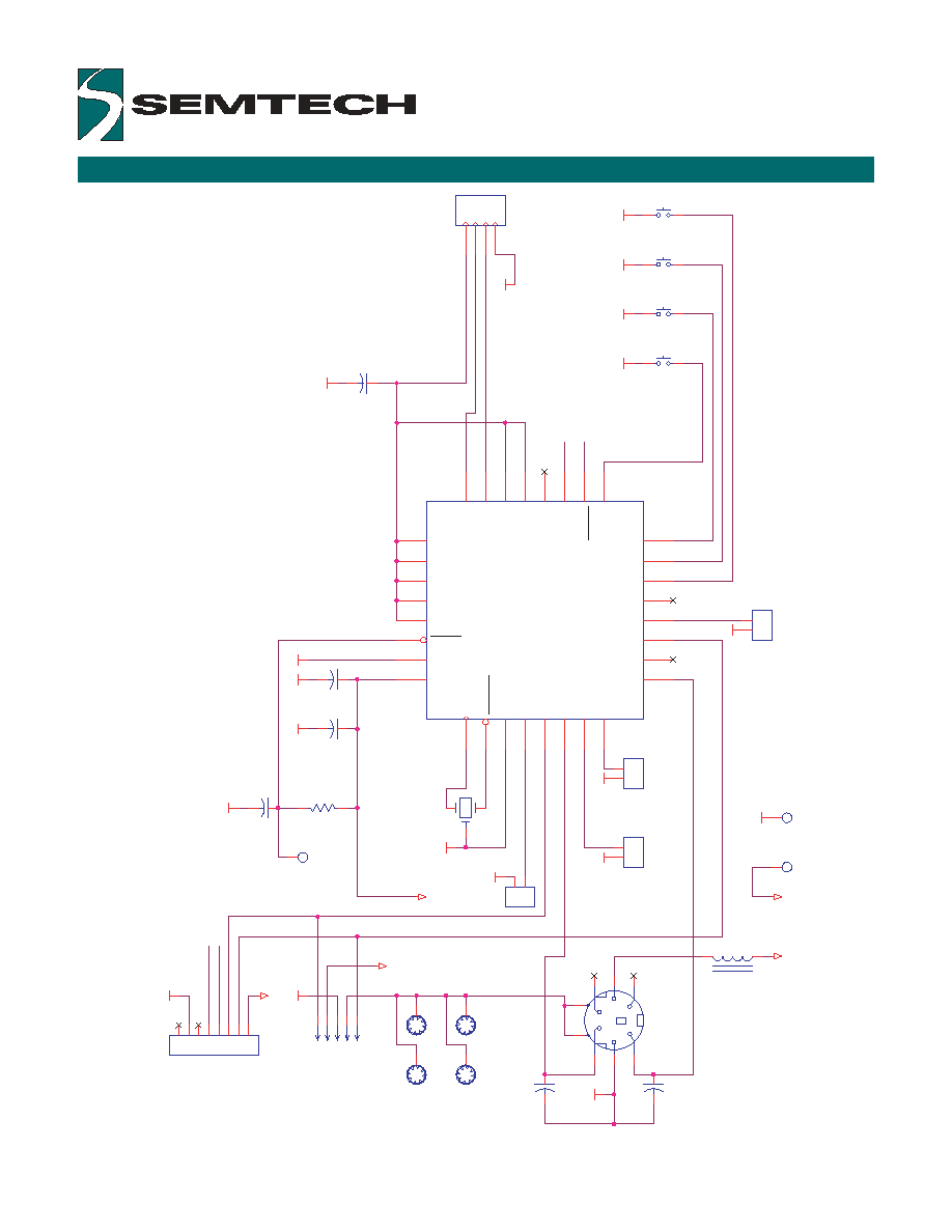
The internal oscillator has a built-in
feedback resistor. Only one
external component is needed for
clock generation. Semtech
recommends a 4.00 MHz ceramic
resonator with built-in load
capacitors (AVX PBRC-4.00BR or
equivalent).
The button inputs (pins 22-25)
have built-in pull-up resistors. No
additional components are
required. However, if high levels of
ESD and EMI are expected, then
series protection resistors (47
Ohms to 1K Ohms) are
recommended between the
switches and the switch inputs on
the SH1211.
PIN DESCRIPTION NOTES
HULAPOINTTM & ANALOG
These pin descriptions and the
schematic on the next page apply
to a circuit with he Fujitsu
Takamisawa FID-828 Hall-effect
sensor (HulaPointTM) or an analog
joystick sensor (like the CTS 252
resistive sensor).
With a HulaPointTM or analog
joystick sensor, the SH1211
supports wait mode and typically
consumes less than 3 mA in
standby.
See also the HulaPointTM sensor
orientation diagram toward the end
of this data sheet.
Copyright ©1995-2003 Semtech Corporation
SH1211 data sheet v1.10 (2003-07)
www.semtech.com
5
SCHEMATIC FOR THE SH1211 MOUSECODER® WITH ANALOG JOYSTICK SENSOR
E
X
T_M_DATA
_
O
S
COUT
O
SCIN
SHIELD
EXT_M
_CLOCK
TX
D
TX
D
INTS
E
L
RTS
M_DA
T
A
INTS
E
L
M
_
C
LOCK
CTS
M
_
C
LOCK
M_DA
T
A
VCC
VCC
GND
GND
GND
GND
GND
GND
GND
GND
GND
GND
VCC
GND
VCC
VCC
GND
GND
GND
GND
GND
GND
GND
GND
Mo
u
n
t
i
n
g
ho
l
e
s
PS
/
2
D
A
T
A
SH
I
E
L
D
GN
D
+5
V
PS
/
2
C
L
O
C
K
1206
1206
C1
47pF
J4
CON2
1
2
JP
2
FFCC4
1
2
3
4
C6
1 µF
C2
47pF
SW4
R
i
ght
C4
100 nF
SW1
Down
SW2
Left
Y1
C3
0
.
01uF
JP
3
S
5
B
_PH_K
1
2
3
4
5
JP
1
M
D
IN6_SH
6
4
2
5
3
1
7
8
R1
100K
J5
CON8
1
2
3
4
5
6
7
8
SH
1
J2
CON2
1
2
L1
1
2uH
SH
6
J1
CON2
1
2
C5
10 µF
U1
32-Pin LQF
P
SH12
11-FG
SWPWR0
1
SWPWR1
2
SWPWR2
3
SWPWR3
4
VREF
5
RESET
6
VSS2
7
VDD
8
OSCIN
9
OSCOUT
10
VSS
11
XYSWP
12
MCLK
13
EMDAT
14
XINV
15
YINV
16
EMCLK
17
SENSEL1
18
MDAT
19
BCONF
20
SENSEL2
21
DB
22
LB
23
MB / UB
24
RB
25
PS2SEL
26
TXD
27
SCLK
28
SWPWR4
29
SWPWR5
30
YAD
31
XAD
32
SH
2
SW3
Middle/Up
J3
CON2
1
2
4.00 MHz
AVX# PBRC-4.00BR
or eqivalent