 | –≠–Ľ–Ķ–ļ—ā—Ä–ĺ–Ĺ–Ĺ—č–Ļ –ļ–ĺ–ľ–Ņ–ĺ–Ĺ–Ķ–Ĺ—ā: CXG1121TN | –°–ļ–į—á–į—ā—Ć:  PDF PDF  ZIP ZIP |

≠ 1 ≠
E01661-PS
Sony reserves the right to change products and specifications without prior notice. This information does not convey any license by
any implication or otherwise under any patents or other right. Application circuits shown, if any, are typical examples illustrating the
operation of the devices. Sony cannot assume responsibility for any problems arising out of the use of these circuits.
CXG1121TN
16 pin TSSOP (Plastic)
SP4T GSM/GPRS Dual-Band Antenna Switch + Logic
Description
The CXG1121TN is one of a range of low insertion
loss, high power MMIC antenna switches for GSM/
GPRS dual-band application. The low insertion loss
on transmit means increased talk time as the Tx
power amplifier can be operated at a lower output
level. On-chip logic reduces component count and
simplifies PWB layout by allowing direct connection
of the switch to digital base band control lines with
CMOS logic levels.
This switch is an SP4T, one antenna can be routed
to either of the 2 Tx or 2 Rx ports. It requires 3 CMOS
control lines (Tx/Rx, GSM900/1800 and Standby).
The Sony GaAs JFET process is used for low
insetion loss. An evaluation PWB is available.
Features
∑ Insertion loss (Tx) 0.5dB typical at 34dBm (GSM900)
∑ 3 CMOS compatible control lines
∑ Low second harmonic, ≠40dBm typical, at 34dBm (GSM900)
∑ Small package size: 16-pin TSSOP (3.9mm
◊
4.1mm
◊
1.2mm)
Applications
∑ Dual-band handsets using combinations of GSM900/GSM1800/GSM1900
∑ GPRS class 12 handsets
Structure
GaAs J-FET MMIC
GaAs MMICs are ESD sensitive devices. Special handling precautions are required. The IC will be damaged in
the range from 100 to 200V @200pF 0
and below 1000V @100pF 1500
.
Absolute Maximum Ratings (Ta = 25įC)
∑ Bias voltage
V
DD
7
V
∑ Control voltage
V
CTL
5
V
∑ Operating temperature
Topr
≠20 to +80
įC

≠ 2 ≠
CXG1121TN
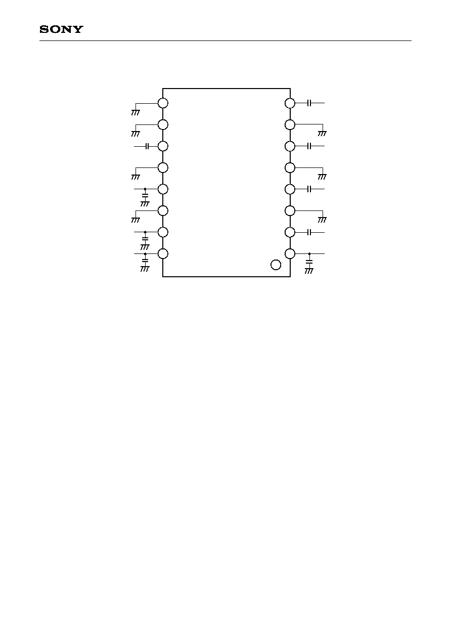
Pin Configuration
Tx1
GND
Tx2
GND
Rx1
GND
Rx2
STDBY
GND
GND
ANT
GND
V
DD
GND
Band Select
Tx/Rx
1
2
3
4
5
6
7
8
9
10
11
12
13
14
15
16
Truth Table
Band select
H
L
L
H
--
On Pass
ANT ≠ Tx1 DCS1800
ANT ≠ Tx2 GSM900
ANT ≠ Rx1 GSM900/DCS1800
ANT ≠ Rx2 GSM900/DCS1800
OFF
Tx (H) / Rx (L)
H
H
L
L
--
Standby
H
H
H
H
L

≠ 3 ≠
CXG1121TN
Electrical characteristics
(Ta = 25įC)
Unit
dB
dB
dB
dB
dB
dB
dB
dB
dBm
dBm
dBm
dBm
dBm
dBm
ĶA
mA
ĶA
Max.
0.7
0.8
0.75
0.9
≠36
≠30
≠36
≠30
120
1.0
Typ.
0.5
0.6
0.55
0.7
20
17
20
20
1.2
≠40
≠34
≠40
≠34
36
36
80
0.5
90
Min.
Condition
1
2
3
4
3
4
1
2
1
1
2
2
1
2
V
CTL
= 3V
STBY = H
STBY = L
Port
Tx2 ≠ ANT
Tx1 ≠ ANT
ANT ≠ Rx1
ANT ≠ Rx2
ANT ≠ Tx1
ANT ≠ Tx2
Tx2 ≠ Rx1, Rx2
Tx1 ≠ Rx1, Rx2
GSM Tx ≠ ANT
DCS Tx ≠ ANT
GSM Tx ≠ ANT
DCS Tx ≠ ANT
Symbol
IL
ISO
VSWR
2fo
3fo
2fo
3fo
P
1dB
I
CTL
I
DD
I
IK
Item
Insertion loss
Isolation
VSWR
Harmonics
P
1dB
compression input
power
Control current
Supply current
Leakage current
Electrical characteristics are measured with all RF ports terminated in 50
.
Harmonics measured with Tx inputs harmonically matched. The use of harmonic matching is recommended
to ensure optimum performance.
1
Power incident on GSM Tx, Pin = 34dBm, 880 to 915MHz, V
DD
= 5.0V, GSM Tx enabled
2
Power incident on DCS Tx, Pin = 32dBm, 1710 to 1785MHz, V
DD
= 5.0V, DCS Tx enabled
3
Power incident on ANT, Pin = 10dBm, 925 to 960MHz, V
DD
= 5.0V, GSM Rx enabled
4
Power incident on ANT, Pin = 10dBm, 1805 to 1880MHz, V
DD
= 5.0V, DCS Rx enabled
Supply Voltage Value (V
DD
)
Mode
GSM/DCS Tx
GSM/DCS Rx
Min.
4.5
2.7
Typ.
5
3
Max.
5.7
4
Unit
V
V
Logic
High
Low
Min.
2.4
0
Typ.
2.8
Max.
3.2
0.4
Unit
V
V
CMOS Logic Value
≠ 4 ≠
CXG1121TN
Recommended Circuit
1
2
3
4
5
6
7
8
9
10
11
12
13
14
15
16
47pF
100pF
22pF
47pF
22pF
100pF
100pF
100pF
47pF
Tx1
GND
Tx2
GND
Rx1
GND
Rx2
STDBY
GND
GND
ANT
GND
V
DD
GND
Band Select
Tx/Rx
Note) Capacitors are required on all RF ports for DC blocking (22pF ≠ 47pF). Decoupling capacitors are
required on V
DD
and on control lines (100pF).

≠ 5 ≠
CXG1121TN
Application Note (1)
Operating from Regulated Supplies between 3V and 2.7V
CXG1121TN
Logic Lines
Tx1
ANT
Tx2
Rx1
Rx2
V
DD
2
4
6
8
11
C
1
D
R
Timeslot
waveform
Regulated supply
between 3V and 2.7V
V
DD
between
5.7V and 4.5V
during Tx
Additional components
C: 0603 CAP ĶF
2
R: 200R
D: Low Turn-on voltage diode
13
Technique
Allows use of CXG1121TN SP4T in handsets with regulated supplies between 3V and 2.7V.
The CXG1121TN is for 5V nominal battery voltage but works well down to a V
DD
of 4.5V.
This technique is only necessary for Tx modes.
Fundamentally, the timeslot waveform is added to the supply voltage to give a V
DD
between 5.7V and 4.5V
(depending on supply) during Tx modes.
This technique is suitable for up to 4 consecutive Tx timeslots (i.e.GPRS Class 12).
1
This waveform may be taken from the PA ramping input (or drain supply in case of drain power control) or
via the Tx ON/OFF logic.
2
Minimum and recommended value of capacitance C depends on GPRS class and is given by the following
table.
Number of consecutive
Tx timeslots
Minimum and recommended
value of capacitance C (ĶF)
1
2
4
1.0
2.0
2.0

≠ 6 ≠
CXG1121TN
Application Note (2)
Impedance Matching for Harmonic Minimization
This note outlines the method used to find the source impedance to present to a transmit port at the second
harmonic frequency (2fo) to reduce the second harmonic level at the antenna.
This should be carried out for a set of devices that represent the process variants. This way a compromise can
be found that suits all variants.
The necessary equipment is shown immediately below.
Signal
Generator
B.P.F.
10dB
Coupler
Power Meter
Diplexer
DC Block
D.U.T.
DC Block
Spectrum
Analyzer
Load Pull
Tuner
Fundamental, fo
Second Harmonic, 2fo
The device should be mounted on a PWB with 50
tracks running from all RF pins to SMA connectors on the
PWB edge (DUT). All ports should be externally DC blocked and unused ports should be terminated in 50
. All
measurements should be performed at the incident powers for which the harmonic levels are specified in this
document.
The 2nd harmonic level at the antenna port is measured using the spectrum analyzer and the vertical and
horizontal position of the load pull stub adjusted such that this level is minimized.
The device should then be removed from the board and an SMA connector mounted such that the source
impedance seen by the transmit port at 2fo can be measured using a VNA.
Measurements should be de-embedded to the end of the SMA center pin.
A network should then be designed to match the impedance of the low pass filter (LPF), which usually comes
in front of the device, to the 2fo source impedance that gives sufficiently reduced 2fo levels for all devices
measured.
The network should be designed to maintain a good match and insertion loss at the fundamental frequency.
≠ 7 ≠
CXG1121TN
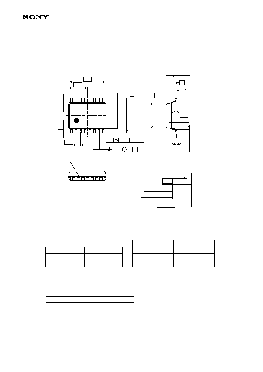
Package Outline Unit: mm
SONY CODE
EIAJ CODE
JEDEC CODE
PACKAGE MATERIAL
LEAD TREATMENT
LEAD MATERIAL
PACKAGE MASS
EPOXY RESIN
SOLDER PLATING
COPPER ALLOY
PACKAGE STRUCTURE
0.03g
TSSOP-16P-L01
16PIN TSSOP (PLASTIC)
0.2 Ī 0.02
0.22 ≠ 0.03
+ 0.036
0.1 Ī
0.01
0.12
≠
0.02
+ 0.026
DETAIL B
X
X
0.1
1
0.5
0.08
S A
M
0.1
A B
X4
S
B
0.2
A B
X2
S
0.1
16
A
2.05
4.1
9
0į to 8į
2.9
3.9
0.1 Ī 0.05
0.45 Ī
0.1
0.25
(3.0)
0.08 S
S
1.2MAX
B
8
Sony Corporation
LEAD PLATING SPECIFICATIONS
ITEM
LEAD MATERIAL
COPPER ALLOY
SOLDER COMPOSITION
Sn-Bi Bi:1-4wt%
PLATING THICKNESS
5-18Ķm
SPEC.