Preliminary Data
This is preliminary information on a new product now in development or undergoing evaluation. Details are subject to
change without notice.
July 2006
Rev 1
1/18
18
PD84001
RF power transistor
The LdmoST plastic family
General features
Excellent thermal stability
Common source configuration
Broadband performances P
OUT
= 1W with
15dB gain @ 870MHz
Plastic package
ESD protection
Supplied in tape and reel
In compliance with the 2002/93/EC european
directive
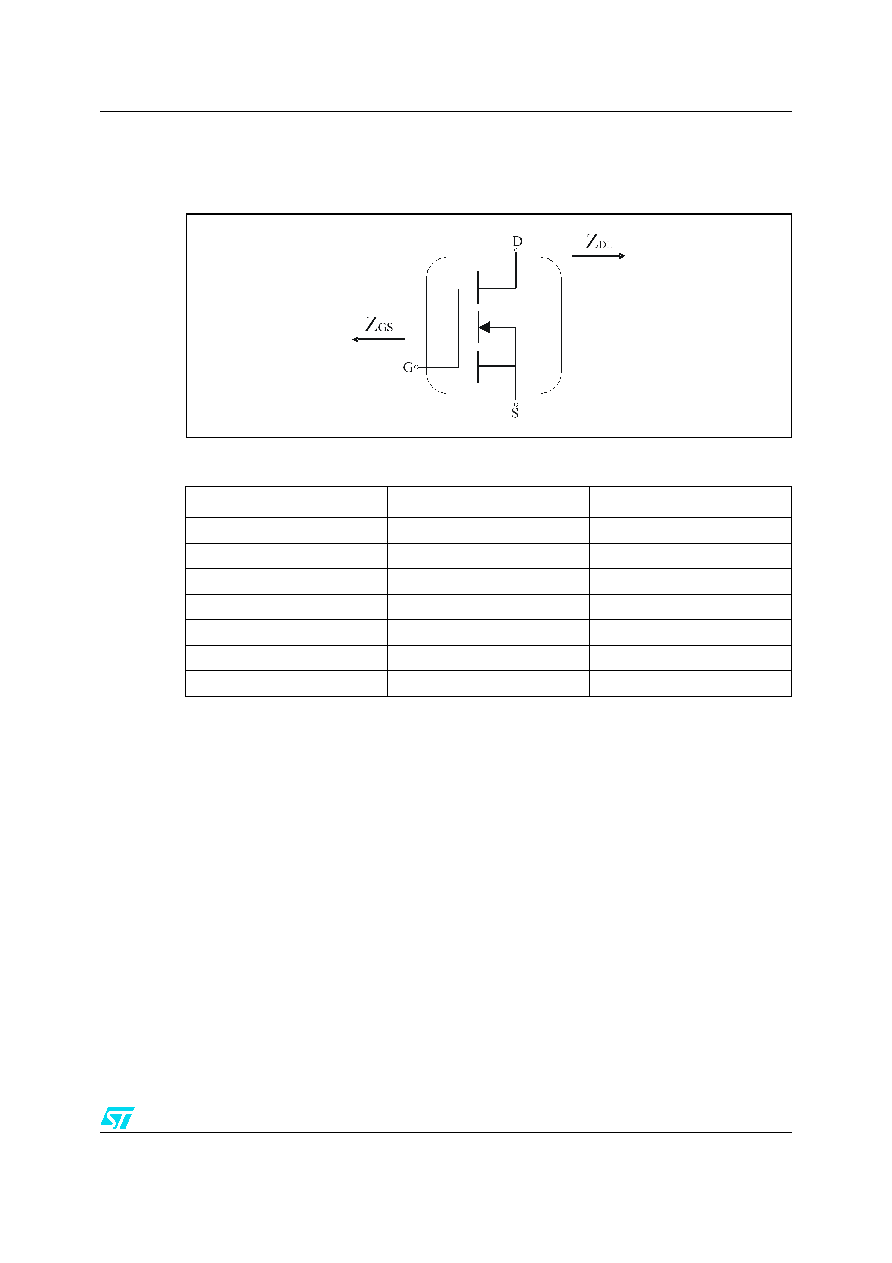
Description
The PD84001 is a common source N-Channel,
enhancement-mode lateral Field-Effect RF power
transistor. It is designed for high gain, broad band
commercial and industrial applications. It
operates at 7V in common source mode at
frequencies of up to 1GHz.
PD84001's superior gain and efficiency makes it
an ideal solution for portable radio and UHF RFID
reader.
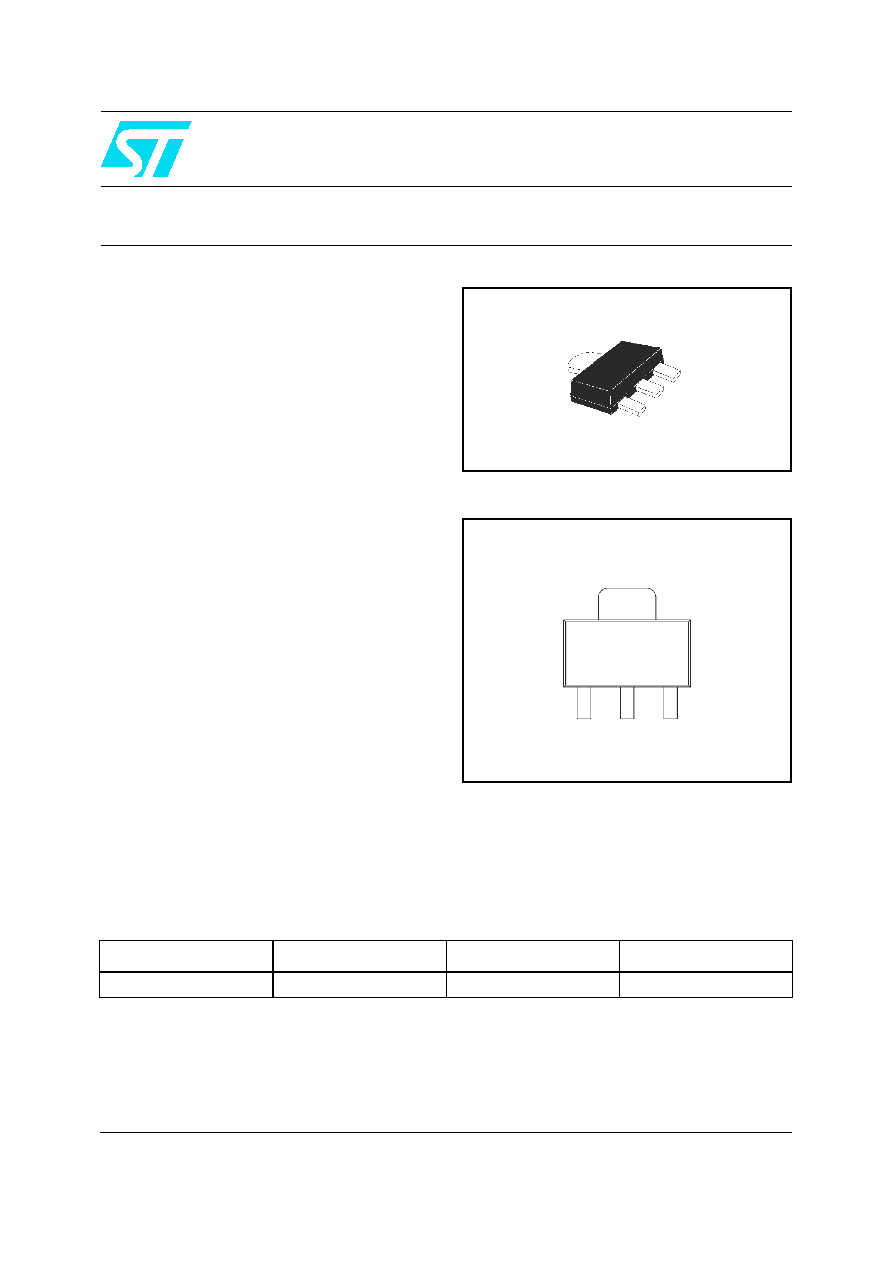
Pin connection
SOT-89
Source
Gate
Source
Drain
www.st.com
Order codes
Part number
Marking
Package
Packaging
PD84001
84001
SOT-89
Tape and reel

Contents
PD84001
2/18
Contents
1
Electrical data . . . . . . . . . . . . . . . . . . . . . . . . . . . . . . . . . . . . . . . . . . . . . . 3
1.1
Maximum ratings . . . . . . . . . . . . . . . . . . . . . . . . . . . . . . . . . . . . . . . . . . . . 3
1.2
Thermal data . . . . . . . . . . . . . . . . . . . . . . . . . . . . . . . . . . . . . . . . . . . . . . . 3
2
Electrical characteristics . . . . . . . . . . . . . . . . . . . . . . . . . . . . . . . . . . . . . 4
2.1
Static . . . . . . . . . . . . . . . . . . . . . . . . . . . . . . . . . . . . . . . . . . . . . . . . . . . . . 4
2.2
Dynamic . . . . . . . . . . . . . . . . . . . . . . . . . . . . . . . . . . . . . . . . . . . . . . . . . . . 4
2.3
ESD protection characteristics . . . . . . . . . . . . . . . . . . . . . . . . . . . . . . . . . . 4
2.4
Moisture sensitivity level . . . . . . . . . . . . . . . . . . . . . . . . . . . . . . . . . . . . . . . 4
3
Impedance . . . . . . . . . . . . . . . . . . . . . . . . . . . . . . . . . . . . . . . . . . . . . . . . . 5
4
Typical performance . . . . . . . . . . . . . . . . . . . . . . . . . . . . . . . . . . . . . . . . . 6
5
Test circuit . . . . . . . . . . . . . . . . . . . . . . . . . . . . . . . . . . . . . . . . . . . . . . . . 10
6
Package mechanical data . . . . . . . . . . . . . . . . . . . . . . . . . . . . . . . . . . . . 11
6.1
Thermal Pad and Via design . . . . . . . . . . . . . . . . . . . . . . . . . . . . . . . . . . 13
6.2
Soldering profile . . . . . . . . . . . . . . . . . . . . . . . . . . . . . . . . . . . . . . . . . . . . 14
7
Revision history . . . . . . . . . . . . . . . . . . . . . . . . . . . . . . . . . . . . . . . . . . . 16
PD84001
Electrical data
3/18
1 Electrical
data
1.1 Maximum
ratings
1.2 Thermal
data
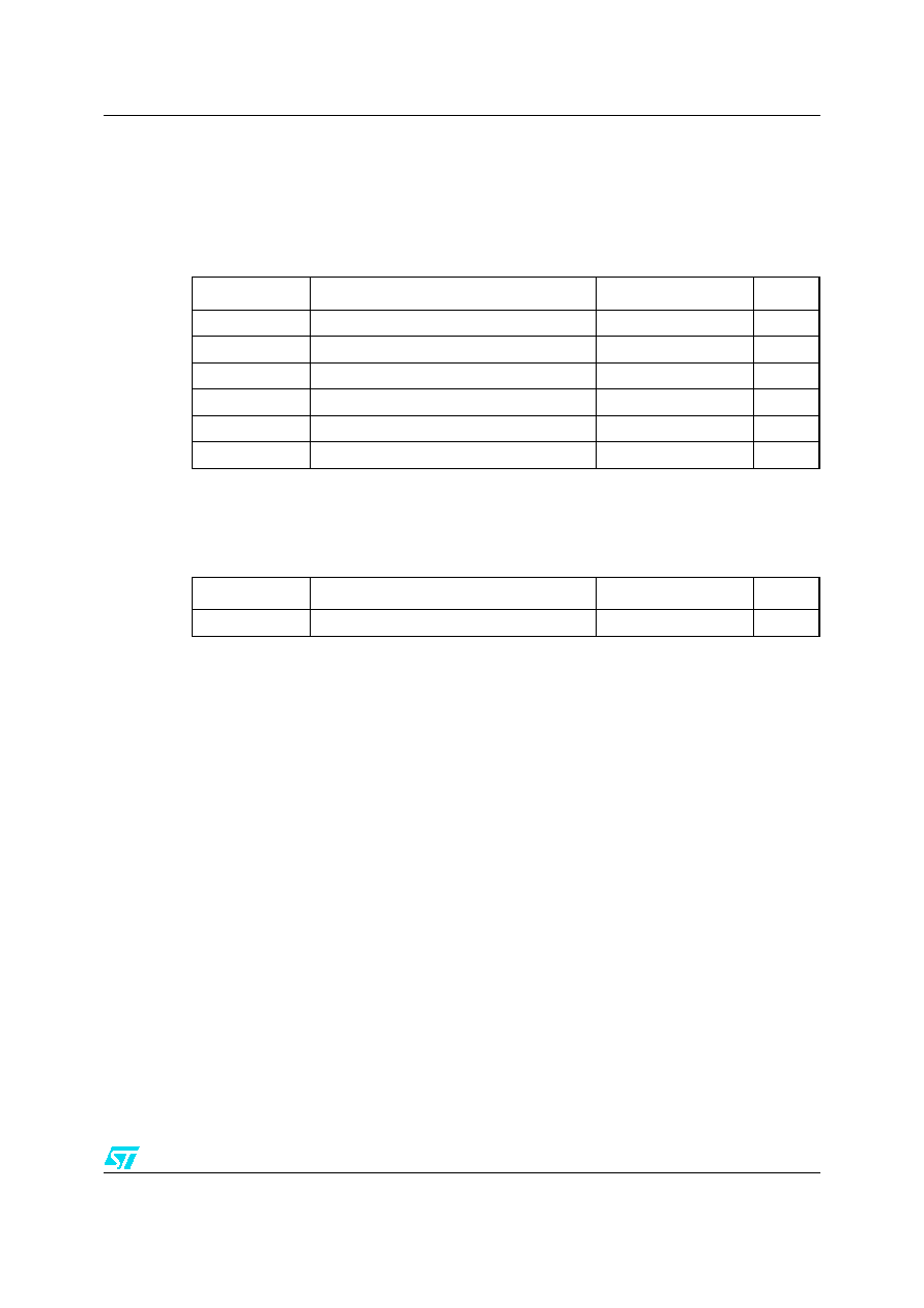
Table 1.
Absolute maximum ratings (T
CASE
= +25�C)
Symbol
Parameter
Value
Unit
V
(BR)DSS
Drain-source voltage
25
V
V
GS
Gate-source voltage
-0.5 to +15
V
I
D
Drain current
1.5
A
P
DISS
Power dissipation
6
W
T
J
Max. operating junction temperature
150
�C
T
STG
Storage temperature
-65 to +150
�C
Table 2.
Thermal data
Symbol
Parameter
Value
Unit
R
thJC
Junction - case thermal resistance
21
�C/W

Electrical characteristics
PD84001
4/18
2 Electrical
characteristics
T
CASE
= +25
o
C
2.1 Static
2.2 Dynamic
2.3 ESD
protection
characteristics
2.4 Moisture
sensitivity
level
Table 3.
Static
Symbol
Test conditions
Min.
Typ.
Max.
Unit
I
DSS
V
GS
= 0 V
V
DS
= 28 V
1
�A
I
GSS
V
GS
= 15 V
V
DS
= 0 V
1
�A
V
GS(Q)
V
DS
= 10 V
I
D
= 250
�A
2.0
3.0
5.0
V
V
DS(ON)
V
GS
= 10 V
I
D
= 0.4 A
0.5
V
C
ISS
V
GS
= 0 V
V
DS
= 7 V
f = 1 MHz
14.7
pF
C
OSS
V
GS
= 0 V
V
DS
= 7 V
f = 1 MHz
13.3
pF
C
RSS
V
GS
= 0 V
V
DS
= 7 V
f = 1 MHz
1.3
pF
Table 4.
Dynamic
Symbol
Test conditions
Min.
Typ.
Max.
Unit
P
OUT
V
DD
= 7.5 V, I
DQ
= 50 mA, P
IN
= 17dBm, f = 870 MHz
30
31
dBm
G
PS
V
DD
= 7.5 V, I
DQ
= 50 mA, P
OUT
= 30dBm, f = 870 MHz
13
15
dB
h
D
V
DD
= 7.5 V, I
DQ
= 50 mA P
IN
= 17dBm, f = 870 MHz
55
60
%
Load
mismatch
V
DD
= 7.5 V, I
DQ
= 50 mA, P
OUT
= 1W, f = 870 MHz
All phase angles
20:1
VSWR
Table 5.
ESD protection characteristics
Test conditions
Class
Human body model
2
Machine model
M3
Table 6.
Moisture sensitivity level
Test methodology
Rating
J-STD-020B
MSL 3