ST3917A
ST3917B
SPEECH - TONE/PULSE DIALER - LED INDICATOR
July 1996
SPEECH CIRCUIT
.
2 TO 4 WIRES CONVERSION
.
PRESENT THE PROPER DC PATH FOR THE LINE
CURRENT AND THE FLEXIBILITY TO ADJUST IT
AND ALLOWPARALLEL PHONE OPERATION
.
SYMMETRICAL HIGH IMPEDANCE MICRO-
PHONE INPUTS SUITABLE FOR DYNAMIC,
ELECTRET OR PIEZOELECTRIC TRANSDUCER
.
ASYMMETRICAL EARPHONE OUTPUT SUIT-
ABLE FOR DYNAMIC TRANSDUCER
.
LINE LOSS COMPENSATION FIXED INTER-
NALLY BY A.G.C.
.
INTERNAL MUTING TO DISABLE SPEECH
DURING DIALING AND EXTERNAL MUTING
TO DISABLE TRANSMIT AMPLIFIER DURING
CONVERSATION MODE
.
LED INDICATOR EITHER FOR KEYBOARD ILLU-
MINATION (OR ON-LINE INDICATION) DURING
DIALING AND CONVERSATION OR FOR TONE
MODE INDICATION, THROUGH MU/MFI PIN
DIALER CIRCUIT
.
STORE UP TO 32 DIGITS FOR LAST NUMBER
REDIAL BUFFER, LNR IS INHIBITED IF THERE
ARE MORE THAN 32 DIGITS STORED
.
ALLOWMIXED MODE DIALING IN PULSE MODE
.
PACIFIER TONE PROVIDES AUDIBLE INDI-
CATION OF VALID KEY PRESSED IN A BUZZ-
ER OR/AND IN THE EARPHONE
.
TIMED PABX PAUSE / 10PPS PULSE RATE
.
MAKE/BREAK RATIO : 40/60 (ST3917A) AND
33/67 (ST3917B)
.
4 SELECTABLE OPTIONS ON FLASH DURA-
TION AND SOFTSWITCH INHIBITION IN ONE
OF THE OPTION WITH 100ms FLASH TIMING
.
2 SELECTABLE OPTIONS : TRANSMIT MUTE
TOGETHER WITH LED FOR KEYBOARD ILLUMI-
NATION OR LED FOR TONE MODE INDICATION
.
CONTINUOUS TONE FOR EACH DIGIT UNTIL
KEY RELEASE
.
USES INEXPENSIVE 3.579545MHz CERAMIC
RESONATOR
.
POWERED FROM TELEPHONE LINE, LOW
OPERATING VOLTAGE FOR LONG LOOP AP-
PLICATION
DESCRIPTION
The device consists of the speech and the dialer func-
tions. It provides the DC line interface circuit that termi-
nates the telephone line, analog amplifier for speech
transmission and necessary signals for either DTMF
and pulse dialing. When mated with a tone ringer, a
complete telephonecan be producedwith just two ICs.
TheDC lineinterfacecircuit developsits ownlinevoltage
acrossthedeviceandit is adjustableby external resistor
to suit different country's specification. A built-in LED
driver can deliver excess line current to external LED
indicator(s) during dialing and speech mode. The
LED(s) can be used either for keyboard illumination
purpose or for tone mode indication during softswitch
and mixed mode dialing by connecting MU/MFI pin to
VDDandGND or anyrow respectively.The LEDcurrent
is limited to 17mA (typical).
The speech network provides the two to four wires inter-
face,electronic switchingbetweendialingandspeechand
automaticgain control on transmit and receive.
The dialing network buffers up to 32 digits into the LND
memorythatcan be laterredialedwith asinglekeyinput.
Users can store all 13 signalling keys and access
several unique functions with single key entries. These
functions include : Pause, Last Number Dialled (LND),
Softswitch and Flash. (see Figure 1).
The FLASH key simulates a hookflash to transfercalls
or to activate other special features provided by the
PABX or central office.
The PAUSE key stores a timed pause in the number
sequence. Redial is then delayed until an outside line
can be accessed or some other activities occur before
normal signalling resumes. A LND key automatically
redials the last number dialed.
Adedicatedpin MU/MFI is used to select the muting for
transmit amplifier and lighted dial LED for keyboard
illumination or a LED indicator for tonemode indication.
The SEL pin allows selection of any one of the four
possible Flash duration options.
DIP28
(Plastic Package)
ORDER CODES :
ST3917AN - ST3917BN
SO28
(Plastic Package)
ORDER CODES :
ST3917AD - ST3917BD
1/16
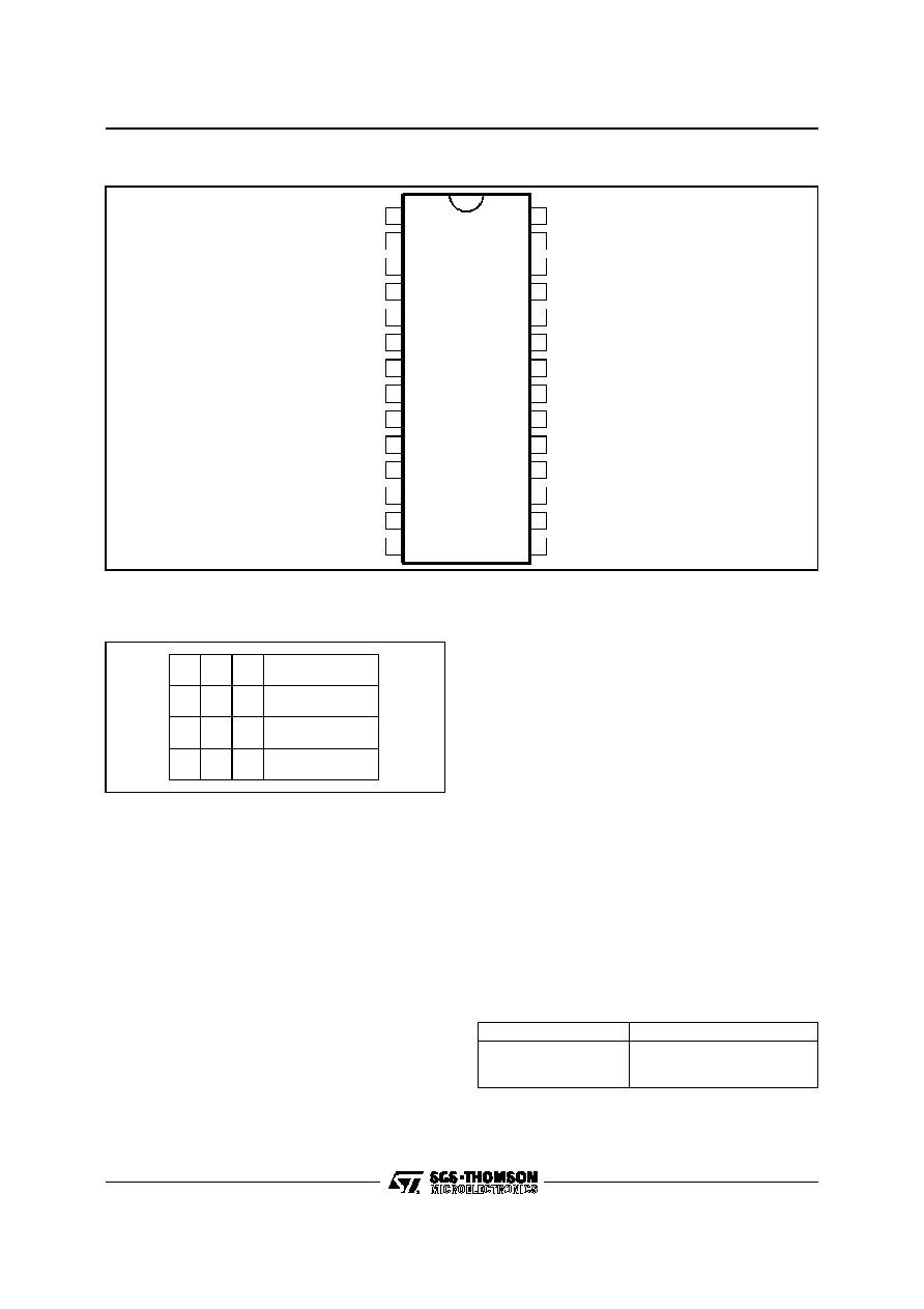
PULSE
R1
R2
R3
R4
MU/MFI
MIC+
1
2
3
4
5
6
7
8
9
10
28
27
26
25
24
23
22
21
20
19
MIC-
GTX
C1
C2
C3
MODE/PT
OSC
SEL
HKS
RXOUT
GND
V
DD
GDTMF
11
12
13
14
18
17
16
15
GRX
RXIN
I
REF
V
CC
LN
ILINE
LED
REG
3917-01.EPS
PIN CONNECTIONS
PIN DESCRIPTION
C1, C2, C3, R4, R3, R2, R1
(Keyboard inputs, Pins 1, 2, 3, 25, 26, 27, 28)
The device interfaces with either the standard 2 of
8 with negative common or the single contact
(Form A) keyboard. Column 4 of the keypad is
connecting to ground.
A valid keypad entry is either a single Row con-
nected to a single Column or GND simultaneously
presented to both a single Row and a single Col-
umn. In its quiescent or standby state, during nor-
mal off-hook operation, the Rows are initialized at
logic level 1 (V
DD
) and the columns are initialized
at logic level 0 (GND). Pulling any row input low
enables the on chip oscillator. Keyboard scanning
then begins.
1
2
3
4
5
6
7
8
9
*
0
#
Flas h
Tone /P ulse
P a us e
LND
3917-02.EPS
Figure 1 : Keyboard Configuration
Scanning consists of Rows and Columns alter-
nately switching high through on chip pullups. After
both a Row and Column keys have been detected,
the debounce counter is enabled and any noise
(bouncing contacts, etc) is ignored for a debounce
period (TKD) of 32ms. At this time, the keyboard is
sampled and if both the Row and Column informa-
tion are valid, the information is buffered into the
LND location.
In the tone mode, if two or more keys in the same
row or if two or more keys in the same column are
depressed a single tone will be output. The tone
will correspond to the common row or common
column for which the two keys were pushed. This
feature is for test purposes, and single tone will not
be redialed. Also in the tone mode, the output tone
is continuous in the manual dialing as long as the
key is pushed. The output tone duration follows the
Table 1. When redialing in the tone mode, each
DTMF output is 90ms duration, and the tone sepa-
ration (inter signal delay) is 90ms.
Table 1 : Output Tone Duration
Key Push Time, T
Tone Output
T < 32ms
32ms < T < 90ms + Tkd
T > 90 ms + Tkd
No output, ignored by the device
90ms duration
Output duration = T - tkd
ST3917A - ST3917B
2/16

SEL (Input, Pin 4)
This is an option selectable pin for four Flash
duration. The four options are summarised in the
table 2.
For option 1, softswitch feature is inhibited. It
means redialed by the LND key in pulse mode will
not repeat the softswitch and subsequent digits,
only pulse digits are dialed out.
Table 2 : Options Selectable for Flash Duration
Options
SEL
Flash (ms)
Softswitch
1
V
DD
100
Inhibited
2
GND
600
Enable
3
Any Row
300
Enable
4
Any Col
100
Enable
OSC (Input, Pin 5)
Only one pin is needed to connect the ceramic
resonator to the oscillator circuit. The other end of
the resonator is connected to GND. The nominal
resonator frequency is 3.579545MHz and any de-
viation from this standard is directly reflected in the
Tone output frequencies. The ceramic resonator
provides the time reference for all circuit functions.
A ceramic resonator with tolerance of
�
0.25% is
recommended.
PULSE (Output, Pin 6)
This is an output consisting of an open drain N-
channel device. During on-hook, pulse output pin
is in high impedance and once off-hook, it will be
pulled high by external resistor.
MODE/PT (Input, Pin 7)
Input (MODE). MODE determines the dialer's de-
fault operating mode. When the device is powered
up or the hookswitch input is switched from on-
hook (V
DD
) to off-hook (GND), the default deter-
mines the signalling mode. A V
DD
connection
defaults to tone mode operation and a GND con-
nection defaults to pulse mode operation.
When dialing in the pulse mode, a softswitch fea-
ture will allow a change to the tone mode whenever
the * or softswitch key (TONE) is depressed. Sub-
sequent * key inputs will cause the DTMF code for
an * to be dialed. The softswitch will only switch
from pulse to tone. The phone will be in pulse mode
only after returning to on-hook and back to off-
hook. Redialed by the LND key will repeat the
softswitch unless the softswitch redial feature is
inhibited.
Output (PT). Pacifier Tone Output. In pulse mode,
all valid key entries activate the pacifier tone. In
tone mode, any non DTMF entry (FLASH, PAUSE,
LND, TONE) activates the pacifier tone. The paci-
fier tone provides audible feedback, confirmingthat
the key has been properly entered and accepted.
It is a 500Hz square wave activated upon accep-
tance of valid key input after the 32ms debounce
time.
The square wave terminates after 75ms typically or
when the valid key is no longer present. The pacifier
tone signal is simultaneously sent to the earphone
and the buzzer. The buzzer can be removed with-
out affecting this function. The resistor value set on
MODE/PT pin determines the level of the pacifier
tone in the earphone.
HKS (Input, Pin 8)
This is the hookswitch input to the device. It is a
CMOS input with a high pull up internal resistance
and must be switched high or open for on-hook
operation and low for off-hook operation. A transi-
tion on this input causes the on-chip logic to initial-
ize, terminating any operation in progress at the
time. The signalling mode defaults to the mode
selected at MODE/PT pin. Figures 2, 3 and 4, 5
illustrate the timing for this pin.
GND (Pin 9)
GND is the negative line terminal of the device.This
is the voltage reference for all specifications.
RXOUT, GRX, RXIN (Pins 10, 11 and 12)
The receive amplifier has one input RXIN and a non
inverting output RXOUT. Amplification from RXIN
to RXOUT is typically 31dB and it can be adjusted
between 21dB and 41dB to suit the sensitivity of
the earphone used. The amplification is propor-
tional to the external resistor connected between
GRX and RXOUT. For the hearing impaired, a
specific application to offer 17dB additional gain at
3kHz is permitted.
I
REF
(Pin 13)
An external resistor of 3.6k
connected between
IREF and GND will set the internal current level.
Any change of this resistor value will influence the
microphone gain, DTMF gain, earphone gain and
sidetone level.
V
CC
(Pin 14)
V
CC
is the positive supply of the speech network. It
can be stabilized by a decoupling capacitor be-
tween V
CC
and GND. The V
CC
supply voltage may
also be used to supply external peripheral circuits.
PIN DESCRIPTION (continued)
ST3917A - ST3917B
3/16
LED (Output, Pin 15)
When the MU/MFI pin is connected to either V
DD
or GND, the LED connected to the LED pin, which
functions as a keyboard illumination or off-hook
indicator, will light up when the telephone is off-
hook.
When the MU/MFI pin is connected to any row pins,
the LED connected to LED pin functions as a tone
mode indicator.
From minimum operating line current up to 20mA,
I
LN
-I
CC
is sourced into the LED with a maximum
current limit of 18mA. For line current more than
20mA, this sourced current is limited at 18mA
(typical).
ILINE (Pin 16)
A recommended external resistor of 20
is con-
nected between ILINE and GND. Changing this
resistor value will influence the microphone gain,
DTMF gain, sidetone, maximum output swing on
LN and the DC characteristics, especially in the low
voltage region.
LN (Pin 17)
LN is the positive line terminal of the device.
REG (Pin 18)
The internal voltage regulator has to be decoupled
by a capacitor from REG to GND. The DC charac-
teristics can be changed with an external resistor
connected between LN and REG or between REG
and ILINE.
GTX, MIC-, MIC+ (Pins 19, 20, 21)
The device has a symmetrical microphone inputs.
The amplification from microphone inputs to LN is
51dB at 15mA line current and it can be adjusted
between 43 and 51dB. The amplification is propor-
tional to the external resistor connected between
GTX and REG.
GDTMF (Pin 22)
When the DTMF input is enabled, the microphone
inputs and the receive amplifier input will be muted
and the dialing tone will be sent on the line. The
voltage amplification from GDTMF to LN is 40dB.
Final output level on the LN can be adjusted via the
external resistor connected between GDTMF and
GND through a decoupling capacitor. A confidence
tone is sent to the earphone during tone dialing.
The attenuation of the confidence tone from LN to
RXOUT is -32dB typically. The level of the confi-
dence tone in the earphone can be increased by
adjusting the resistor connected between GDTMF
and GRX pins, the possible range is 20dB.
V
DD
(Pin 23)
V
DD
is the positive supply for the dialing circuit and
it must meet the maximum and minimum voltage
requirements.
MU/MFI (Input, Pin 24)
A logic low input to this pin will disable the transmit
amplifier of the speech circuit. MUTE efficiency is
greater than 60dB. An open circuit to this pin will
enable the transmit amplifier. In this case, LED is
used for keypad lighting.
A connection to any row will disable the transmit
mute function and the LED connected to the LED
pin is used for tone mode indication.
Table 3 : Logic of MU/MFI Pin Indicator
MU/MFI
Pin
Transmit
Muting
LED at Pin 15
OPEN
Active
Lighted Dial Indicator
GND
Muted
Lighted Dial Indicator
Any Row
Not Available
Tone Mode Indicator
PIN DESCRIPTION (continued)
ST3917A - ST3917B
4/16

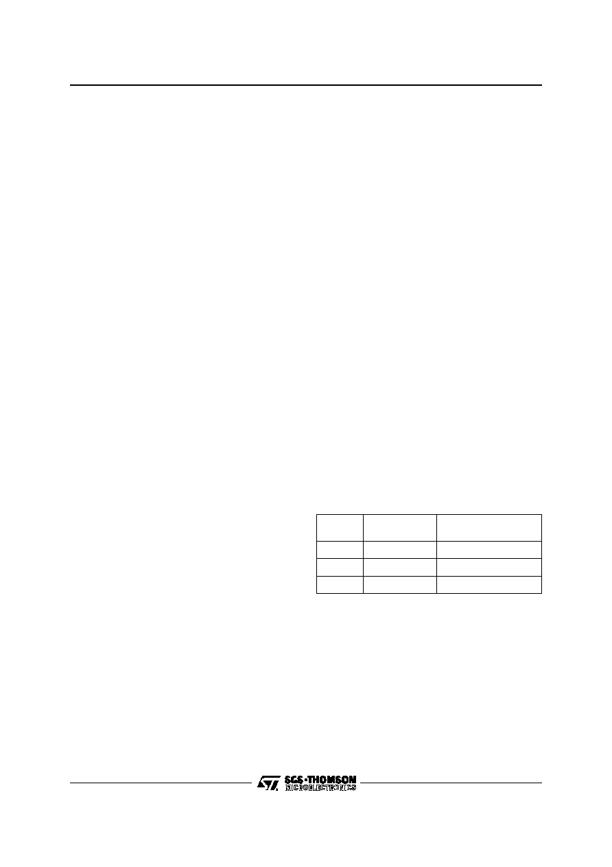
9
10
11
12
13
14
16
18
19
20
21
22
gm
MIC+
MIC-
kI
REF
gm
KI
REF
GDTMF
V1
Ri2
gm
KI
REF
gm
KI
REF
I1
Ri1
GRX
RXOUT
RGRX
+
C9
ILINE/ILED
CONTROL
IREF
I
REF
V
CC
DTMF
GENERATOR
LOGIC
+
DAC
MUTE
OSCILLATOR
KEYBOARD
INTERFACE
PULSE
INTERFACE
RAM
REDIAL
4
67
8
15
17
23
MODE
HKS
SEL
PULSE
LN
LED
V
DD
24
5
OSC
MU/MFI
Ci
Ri
12
3
45
6
78
9
*
0#
Flash
Tone/Pulse
Pause
LND
3.58MHz
Ceramic
RMF
CMF
C14
R14
C10
ST3917A/B
C8
+
D12
R15
LA
LB
R20
RGTX
R21
C20
C11
GTX
ILINE
REG
RXIN
GND
R24
R25
LN
Secret
3917-03.EPS
BLOCK DIAGRAM
ST3917A - ST3917B
5/16