1/13
November 2004
STM1001
Reset Circuit
FEATURES SUMMARY
PRECISION MONITORING OF 3V, 3.3V, and
5V SUPPLY VOLTAGES
OPEN DRAIN RST OUTPUT
140ms RESET PULSE WIDTH (MIN)
LOW SUPPLY CURRENT - 6ĶA (TYP)
GUARANTEED RST ASSERTION DOWN TO
V
CC
= 1.0V
OPERATING TEMPERATURE:
≠40įC to 85įC (Industrial Grade)
LEAD-FREE, SMALL SOT23 PACKAGE
Figure 1. Logic Diagram
Figure 2. Package
Table 1. Signal Names
Figure 3. SOT23-3 Connections
AI09116
V
CC
STM1001
V
SS
RST
V
SS
Ground
RST
Active-Low RESET Output (Open
Drain)
V
CC
Supply Voltage
SOT23-3 (WX)
AI09117
2
3
1
RST
V
CC
V
SS

STM1001
2/13
TABLE OF CONTENTS
FEATURES SUMMARY . . . . . . . . . . . . . . . . . . . . . . . . . . . . . . . . . . . . . . . . . . . . . . . . . . . . . . . . . . . . . 1
Figure 1. Logic Diagram . . . . . . . . . . . . . . . . . . . . . . . . . . . . . . . . . . . . . . . . . . . . . . . . . . . . . . . . . . 1
Figure 2. Package. . . . . . . . . . . . . . . . . . . . . . . . . . . . . . . . . . . . . . . . . . . . . . . . . . . . . . . . . . . . . . . 1
Table 1. Signal Names . . . . . . . . . . . . . . . . . . . . . . . . . . . . . . . . . . . . . . . . . . . . . . . . . . . . . . . . . . 1
Figure 3. SOT23-3 Connections . . . . . . . . . . . . . . . . . . . . . . . . . . . . . . . . . . . . . . . . . . . . . . . . . . . . 1
SUMMARY DESCRIPTION . . . . . . . . . . . . . . . . . . . . . . . . . . . . . . . . . . . . . . . . . . . . . . . . . . . . . . . . . . . 3
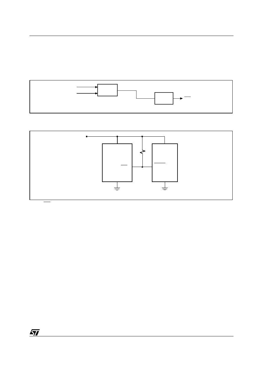
Figure 4. Block Diagram . . . . . . . . . . . . . . . . . . . . . . . . . . . . . . . . . . . . . . . . . . . . . . . . . . . . . . . . . . 3
Figure 5. Hardware Hookup . . . . . . . . . . . . . . . . . . . . . . . . . . . . . . . . . . . . . . . . . . . . . . . . . . . . . . . 3
OPERATION . . . . . . . . . . . . . . . . . . . . . . . . . . . . . . . . . . . . . . . . . . . . . . . . . . . . . . . . . . . . . . . . . . . . . . 4
Reset Output . . . . . . . . . . . . . . . . . . . . . . . . . . . . . . . . . . . . . . . . . . . . . . . . . . . . . . . . . . . . . . . . . . 4
Negative-Going V
CC
Transients . . . . . . . . . . . . . . . . . . . . . . . . . . . . . . . . . . . . . . . . . . . . . . . . . . . 4
Valid /RST Output Down to V
CC
= 0V . . . . . . . . . . . . . . . . . . . . . . . . . . . . . . . . . . . . . . . . . . . . . . . 4
TYPICAL OPERATING CHARACTERISTICS . . . . . . . . . . . . . . . . . . . . . . . . . . . . . . . . . . . . . . . . . . . . 5
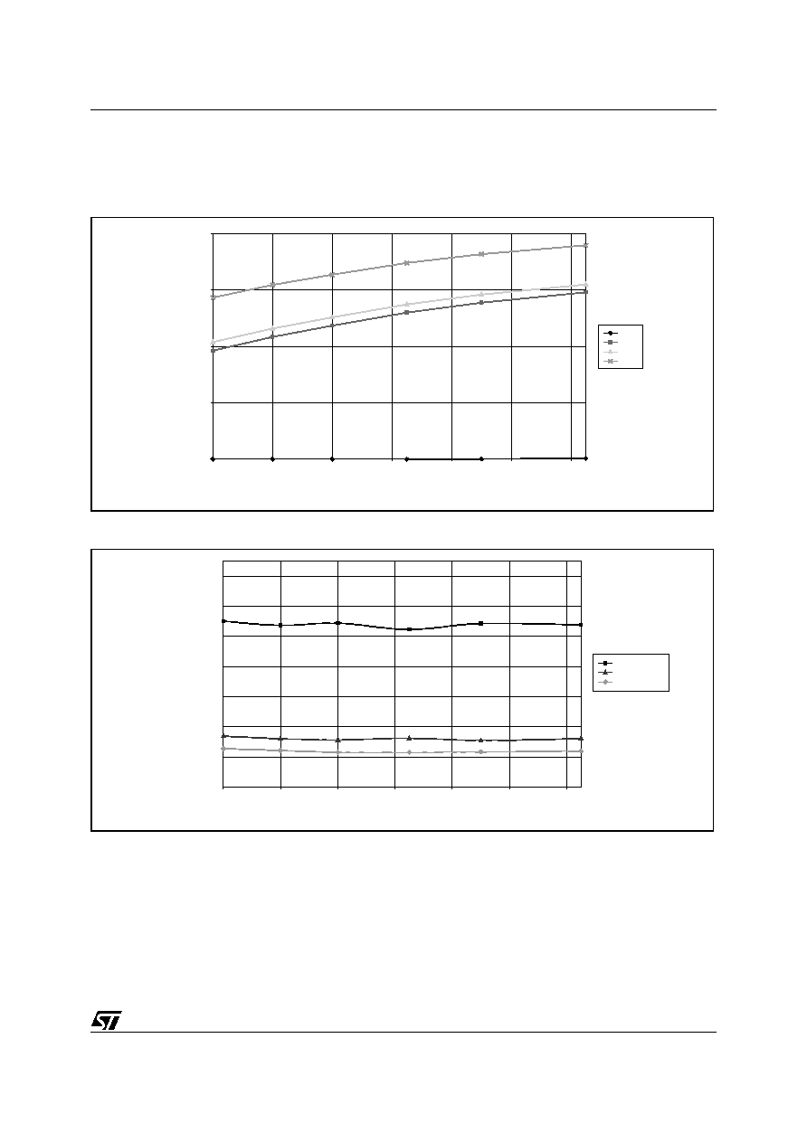
Figure 6. Supply Current vs. Temperature, L/M/R/S/T (no load) . . . . . . . . . . . . . . . . . . . . . . . . . . . 5
Figure 7. Power-down Reset Delay vs. Temperature - V
OD
= V
TH
≠ V
CC
(L/M). . . . . . . . . . . . . . . . 5
Figure 8. Power-down Reset Delay vs. Temperature - V
OD
= V
TH
≠ V
CC
(R/S/T) . . . . . . . . . . . . . . 6
Figure 9. Power-up t
rec
vs. Temperature . . . . . . . . . . . . . . . . . . . . . . . . . . . . . . . . . . . . . . . . . . . . . 6
Figure 10.Normalized Reset Threshold vs. Temperature . . . . . . . . . . . . . . . . . . . . . . . . . . . . . . . . . 7
Figure 11.Max Transient Duration NOT Causing Reset Pulse vs. Reset Comparator Overdrive . . . 7
MAXIMUM RATING. . . . . . . . . . . . . . . . . . . . . . . . . . . . . . . . . . . . . . . . . . . . . . . . . . . . . . . . . . . . . . . . . 8
Table 2. Absolute Maximum Ratings . . . . . . . . . . . . . . . . . . . . . . . . . . . . . . . . . . . . . . . . . . . . . . . . 8
DC and AC PARAMETERS . . . . . . . . . . . . . . . . . . . . . . . . . . . . . . . . . . . . . . . . . . . . . . . . . . . . . . . . . . 8
Table 3. Operating and AC Measurement Conditions . . . . . . . . . . . . . . . . . . . . . . . . . . . . . . . . . . . 8
Figure 12.AC Testing Input/Output Waveforms. . . . . . . . . . . . . . . . . . . . . . . . . . . . . . . . . . . . . . . . . 8
Table 4. DC and AC Characteristics . . . . . . . . . . . . . . . . . . . . . . . . . . . . . . . . . . . . . . . . . . . . . . . . 9
PACKAGE MECHANICAL . . . . . . . . . . . . . . . . . . . . . . . . . . . . . . . . . . . . . . . . . . . . . . . . . . . . . . . . . . 10
Figure 13.SOT23-3 ≠ 3-lead Small Outline Transistor Package Outline . . . . . . . . . . . . . . . . . . . . . 10
Table 5. SOT23-3 ≠ 3-lead Small Outline Transistor Package Mechanical Data . . . . . . . . . . . . . 10
PART NUMBERING . . . . . . . . . . . . . . . . . . . . . . . . . . . . . . . . . . . . . . . . . . . . . . . . . . . . . . . . . . . . . . . 11
Table 6. Ordering Information Scheme . . . . . . . . . . . . . . . . . . . . . . . . . . . . . . . . . . . . . . . . . . . . . 11
Table 7. Marking Description . . . . . . . . . . . . . . . . . . . . . . . . . . . . . . . . . . . . . . . . . . . . . . . . . . . . . 11
REVISION HISTORY. . . . . . . . . . . . . . . . . . . . . . . . . . . . . . . . . . . . . . . . . . . . . . . . . . . . . . . . . . . . . . . 12
Table 8. Document Revision History . . . . . . . . . . . . . . . . . . . . . . . . . . . . . . . . . . . . . . . . . . . . . . . 12

STM1001
4/13
OPERATION
Reset Output
The STM1001 MICROPROCESSOR RESET
CIRCUIT asserts a reset signal to the MCU when-
ever V
CC
goes below the reset threshold (V
RST
).
RST is guaranteed valid down to V
CC
= 1V (0į to
70įC).
During power-up, once V
CC
exceeds the reset
threshold an internal timer keeps RST low for the
reset time-out period, t
rec
. After this interval, RST
returns high.
If V
CC
drops below the reset threshold, RST goes
low. Each time RST is asserted, it stays low for at
least the reset time-out period. Any time V
CC
goes
below the reset threshold, the internal timer clears.
The reset timer starts when V
CC
returns above the
reset threshold. The active-low reset (RST) is an
open drain output.
Negative-Going V
CC
Transients
The STM1001 is relatively immune to negative-go-
ing V
CC
transients (glitches).
Figure 11., page 7
shows typical transient duration versus reset com-
parator overdrive (for which the STM1001 will
NOT generate a reset pulse). The graph was gen-
erated using a negative pulse applied to V
CC
,
starting at 0.5V above the actual reset threshold
and ending below it by the magnitude indicated
(comparator overdrive). The graph indicates the
maximum pulse width a negative V
CC
transient
can have without causing a reset pulse. As the
magnitude of the transient increases (further be-
low the threshold), the maximum allowable pulse
width decreases. Any combination of duration and
overdrive which lies under the curve will NOT gen-
erate a reset signal. Typically, a V
CC
transient that
goes 100mV below the reset threshold and lasts
20Ķs or less will not cause a reset pulse. A 0.1ĶF
bypass capacitor mounted as close as possible to
the V
CC
pin provides additional transient immunity.
Valid /RST Output Down to V
CC
= 0V
When V
CC
falls below 1V, the RST output no long-
er sinks current, but becomes an open circuit. In
most systems this is not a problem, as most MCUs
do not operate below 1V. However, in applications
where RST output must be valid down to 0V, a
pull-down resistor may be added to hold the RST
output low. This resistor must be large enough to
not load the RST output, and still be small enough
to pull the output to ground. A 100K
resistor is
recommended.