 | –≠–ª–µ–∫—Ç—Ä–æ–Ω–Ω—ã–π –∫–æ–º–ø–æ–Ω–µ–Ω—Ç: TS3704 | –°–∫–∞—á–∞—Ç—å:  PDF PDF  ZIP ZIP |

TS3704C,I,M
MICROPOWER QUAD CMOS VOLTAGE COMPARATORS
.
PUSH-PULL CMOS OUTPUT (NO EXTER-
NAL PULL-UP RESISTOR REQUIRED)
.
EXTREMELY LOW SUPPLY CURRENT :
9
µ
A TYP / COMPARATOR
.
WIDE SINGLE SUPPLY RANGE (3V TO 16V)
OR DUAL SUPPLIES (
±
1.5V TO
±
8V)
.
EXTREMELY LOW INPUT BIAS CURRENT :
1pA TYP
.
EXTREMELY LOW INPUT OFFSET
CURRENT : 1pA TYP
.
INPUT COMMON-MODE VOLTAGE RANGE
INCLUDES GND
.
HIGH INPUT IMPEDANCE : 10
12
TYP
.
FAST RESPONSE TIME : 2
µ
s TYP FOR
5mV OVERDRIVE
.
PIN-TO-PIN AND FUNCTIONALLY
COMPATIBLE WITH BIPOLAR LM339
Inverting Input 2
Output 2
Non-inverting Input 2
Output 1
Inverting Input 1
Non-inverting Input 1
CC
V
-
CC
V
1
2
3
4
8
5
6
7
9
10
11
12
13
14
+
Output 3
Output 4
Non-inverting Input 4
Inverting Input 4
Non-inverting Input 3
Inverting Input 3
-
+
-
+
-
+
-
+
PIN CONNECTIONS (top view)
N
DIP14
(Plastic Package)
D
SO14
(Plastic Micropackage)
Æ
January 1999
ORDER CODES
Part Number
Temperature Range
Package
N
D
P
TS3704C
0
o
C, +70
o
C
q
q
q
TS3704I
-40
o
C, +125
o
C
q
q
q
TS3704M
-55
o
C, +125
o
C
q
q
q
Example : TS3704CN
DESCRIPTION
The TS3704 is a micropower CMOS quad voltage
comparator with extremely low consumption
of 9
µ
A typ / comparator (20 times less than bipolar
LM339). The push-pull CMOS output stage allows
power and space saving by eliminating the external
pull-up resistor required by usual open-collector
output comparators.
Thus response times remain similar to the LM339.
P
TSSOP14
(Thin Shrink Small Outline Package)
1/6
T
1
T
2
1
T
T
3
4
R
T
T
T
T
5
6
7
8
T
T
T
9
11
10
T
12
T
17
T
13
T
T
14
15
T
16
T
T
19
20
T
T
18
21
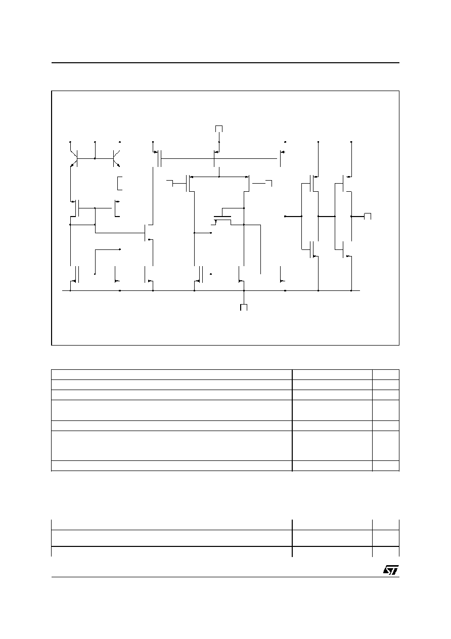
Input -
Input +
Output
CC
V
+
CC
V
-
SCHEMATIC DIAGRAM (for 1/4 TS3704)
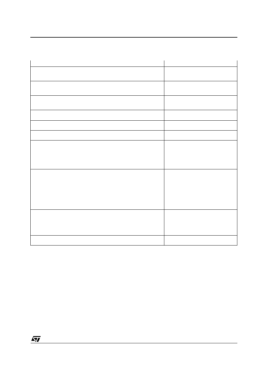
MAXIMUM RATINGS
Symbol
Parameter
Value
Unit
V
CC
+
Supply Voltage - (note 1)
18
V
V
id
Differential Input Voltage - (note 2)
±
18
V
V
i
Input Voltage - (note 3)
18
V
V
O
Output Voltage
18
V
I
O
Output Current
20
mA
T
oper
Operating Free-Air Temperature Range
TS3704C
TS3704I
TS3704M
0 to +70
-40 to +125
-55 to +125
o
C
T
stg
Storage Temperature Range
-65 to +150
o
C
Notes : 1. All voltage values, except differential voltage, are with respect to network ground terminal.
2. Differential voltages are the non-inverting input terminal with respect to the inverting input terminal.
3. The magnitude of the input and the output voltages must never exceed the magnitude of the positive supply voltage.
4. Short circuit from outputs to V
CC
+
can cause excessive heating and eventual destruction.
OPERATING CONDITIONS
Symbol
Parameter
Value
Unit
V
CC
+
Supply Voltage
TS3704C,I
TS3704M
3 to 16
4 to 16
V
V
icm
Common Mode Input Voltage Range
0 to V
CC
+
-1.5
V
TS3704C,I,M
2/6
ELECTRICAL CHARACTERISTICS
V
CC
+
= 5V, V
CC
-
= 0V, T
amb
= 25
∞
C (unless otherwise specified)
Symbol
Parameter
Min.
Typ.
Max.
Unit
V
io
Input Offset Voltage
V
ic
= v
icm min.,
V
CC
+
= 5V to 10V - (note 1)
T
min.
T
amb
T
max
.
1.2
5
6.5
mV
I
io
Input Offset Current - (note 2)
V
ic
= 2.5 V
T
min.
T
amb
T
max
.
1
300
pA
I
ib
Input Bias Current - (note 2)
V
ic
= 2.5 V
T
min.
T
amb
T
max
.
1
600
pA
V
icm
Input Common Mode Voltage Range
T
min.
T
amb
T
max
.
0 to V
CC
+
-1.2
0 to V
CC
+
-1.5
V
CMR
Common-mode Rejection Ratio
V
ic
= V
icm min
.
78
dB
SVR
Supply Voltage Rejection Ratio
V
CC
+
= +5V to +10V
92
dB
V
OH
High Level Output Voltage
V
id
= 1V, I
OH =
-4mA
T
min.
T
amb
T
max
.
4.5
4.3
4.7
V
V
OL
Low Level Output Voltage
V
id
= -1V, I
OL =
4mA
T
min.
T
amb
T
max
.
234
300
375
mV
I
CC
Supply Current (4 comparators)
No load - Outputs low
T
min.
T
amb
T
max
.
36
80
100
µ
A
t
PLH
Response Time Low to High
V
ic
= 0V, f = 10kHz, C
L
= 50pF,
Overdrive = 5mV
Overdrive = 10mV
Overdrive = 20mV
Overdrive = 40mV
TTL Input
1.2
1
0.9
0.8
0.7
µ
s
t
PHL
Response Time High to Low
V
ic
= 0V, f = 10kHz, C
L
= 50pF,
Overdrive =
5mV
Overdrive = 10mV
Overdrive = 20mV
Overdrive = 40mV
TTL Input
2
1.5
0.9
0.7
0.15
µ
s
t
f
Fall time
f = 10kHz, C
L
= 50pF, Overdrive 50mV
30
ns
Note :
1. The specified offset voltage is the maximun value required to drive the output up to 4.5V or down to 0.3V.
2. Maximum values including unavoidable inaccuracies of the industrial test.
TS3704C,I,M
3/6

PACKAGE MECHANICAL DATA
14 PINS - PLASTIC DIP
Dimensions
Millimeters
Inches
Min.
Typ.
Max.
Min.
Typ.
Max.
a1
0.51
0.020
B
1.39
1.65
0.055
0.065
b
0.5
0.020
b1
0.25
0.010
D
20
0.787
E
8.5
0.335
e
2.54
0.100
e3
15.24
0.600
F
7.1
0.280
i
5.1
0.201
L
3.3
0.130
Z
1.27
2.54
0.050
0.100
TS3704C,I,M
4/6

PACKAGE MECHANICAL DATA
14 PINS - PLASTIC MICROPACKAGE (SO)
Dimensions
Millimeters
Inches
Min.
Typ.
Max.
Min.
Typ.
Max.
A
1.75
0.069
a1
0.1
0.2
0.004
0.008
a2
1.6
0.063
b
0.35
0.46
0.014
0.018
b1
0.19
0.25
0.007
0.010
C
0.5
0.020
c1
45
o
(typ.)
D
8.55
8.75
0.336
0.334
E
5.8
6.2
0.228
0.244
e
1.27
0.050
e3
7.62
0.300
F
3.8
4.0
0.150
0.157
G
4.6
5.3
0.181
0.208
L
0.5
1.27
0.020
0.050
M
0.68
0.027
S
8
o
(max.)
TS3704C,I,M
5/6