 | –≠–ª–µ–∫—Ç—Ä–æ–Ω–Ω—ã–π –∫–æ–º–ø–æ–Ω–µ–Ω—Ç: LM3900 | –°–∫–∞—á–∞—Ç—å:  PDF PDF  ZIP ZIP |
LM2900, LM3900
QUADRUPLE NORTON OPERATIONAL AMPLIFIERS
SLOS059 ≠ JULY 1979 ≠ REVISED SEPTEMBER 1990
1
POST OFFICE BOX 655303
∑
DALLAS, TEXAS 75265
D
Wide Range of Supply Voltages, Single or
Dual Supplies
D
Wide Bandwidth
D
Large Output Voltage Swing
D
Output Short-Circuit Protection
D
Internal Frequency Compensation
D
Low Input Bias Current
D
Designed to Be Interchangeable With
National Semiconductor LM2900 and
LM3900, Respectively
description
These devices consist of four independent, high-
gain frequency-compensated Norton operational
amplifiers that were designed specifically to
operate from a single supply over a wide range of
voltages. Operation from split supplies is also
possible. The low supply current drain is
essentially independent of the magnitude of the
supply voltage. These devices provide wide band-
width and large output voltage swing.
The LM2900 is characterized for operation from
≠ 40
∞
C to 85
∞
C, and the LM3900 is characterized
for operation from 0
∞
C to 70
∞
C.
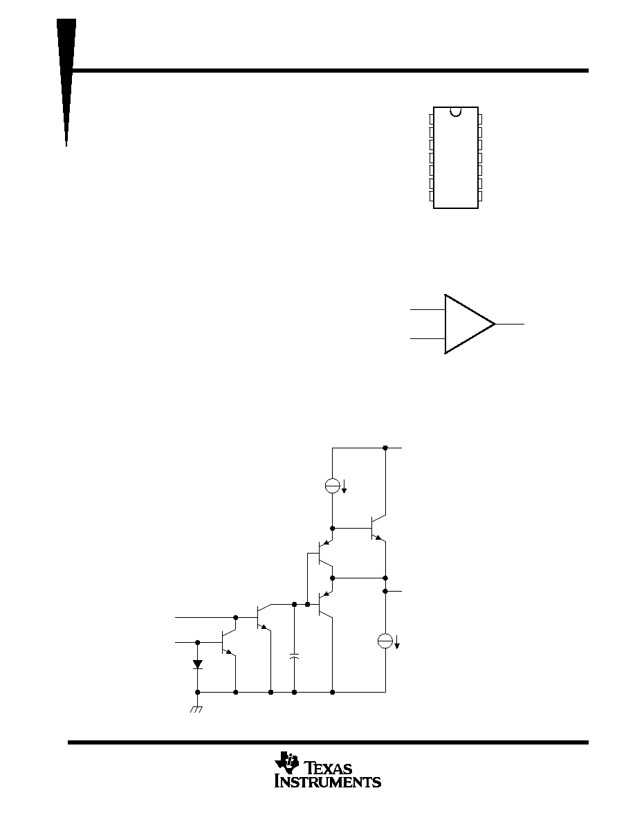
schematic (each amplifier)
Constant
Current
Generator
VCC
200
µ
A
OUT
1.3 mA
IN +
IN ≠
Copyright
©
1990, Texas Instruments Incorporated
PRODUCTION DATA information is current as of publication date.
Products conform to specifications per the terms of Texas Instruments
standard warranty. Production processing does not necessarily include
testing of all parameters.
+
≠
IN +
IN ≠
OUT
1
2
3
4
5
6
7
14
13
12
11
10
9
8
1IN +
2IN +
2IN ≠
2OUT
1OUT
1IN ≠
GND
V
CC
3IN +
4IN +
4IN ≠
4OUT
3OUT
3IN ≠
N PACKAGE
(TOP VIEW)
symbol (each amplifier)
LM2900, LM3900
QUADRUPLE NORTON OPERATIONAL AMPLIFIERS
SLOS059 ≠ JULY 1979 ≠ REVISED SEPTEMBER 1990
2
POST OFFICE BOX 655303
∑
DALLAS, TEXAS 75265
absolute maximum ratings over operating free-air temperature range (unless otherwise noted)
LM2900
LM3900
UNIT
Supply voltage, VCC (see Note 1)
36
36
V
Input current
20
20
mA
Duration of output short circuit (one amplifier) to ground at (or below) 25
∞
C free-air temperature
(see Note 2)
unlimited
unlimited
Continuous total dissipation
See Dissipation Rating Table
Operating free-air temperature range
≠ 40 to 85
0 to 70
∞
C
Storage temperature range
≠ 65 to 150
≠ 65 to 150
∞
C
Lead temperature 1,6 mm (1/16 inch) from case for 10 seconds
260
260
∞
C
NOTES:
1. All voltage values, except differential voltages, are with respect to the network ground terminal.
2. Short circuits from outputs to VCC can cause excessive heating and eventual destruction.
DISSIPATION RATING TABLE
PACKAGE
TA
25
∞
C
POWER RATING
DERATING FACTOR
ABOVE TA = 25
∞
C
TA = 70
∞
C
POWER RATING
TA = 85
∞
C
POWER RATING
N
1150 mW
9.2 mW/
∞
C
736 mW
598 mW
recommended operating conditions
LM2900
LM3900
UNIT
MIN
MAX
MIN
MAX
UNIT
Supply voltage, VCC (single supply)
4.5
32
4.5
32
V
Supply voltage, VCC + (dual supply)
2.2
16
2.2
16
V
Supply voltage, VCC ≠ (dual supply)
≠ 2.2
≠ 16
≠ 2.2
≠ 16
V
Input current (see Note 3)
≠ 1
≠ 1
mA
Operating free-air temperature, TA
≠ 40
85
0
70
∞
C
NOTE 3: Clamp transistors are included that prevent the input voltages from swinging below ground more than approximately ≠ 0.3 V. The
negative input currents that may result from large signal overdrive with capacitive input coupling must be limited externally to values
of approximately ≠ 1 mA. Negative input currents in excess of ≠ 4 mA causes the output voltage to drop to a low voltage. These
values apply for any one of the input terminals. If more than one of the input terminals are simultaneously driven negative, maximum
currents are reduced. Common-mode current biasing can be used to prevent negative input voltages.
LM2900, LM3900
QUADRUPLE NORTON OPERATIONAL AMPLIFIERS
SLOS059 ≠ JULY 1979 ≠ REVISED SEPTEMBER 1990
3
POST OFFICE BOX 655303
∑
DALLAS, TEXAS 75265
electrical characteristics, V
CC
= 15 V, T
A
= 25
∞
C (unless otherwise noted)
PARAMETER
TEST CONDITIONS
LM2900
LM3900
UNIT
PARAMETER
TEST CONDITIONS
MIN
TYP
MAX
MIN
TYP
MAX
UNIT
IIB
Input bias current (inverting input)
II = 0
TA = 25
∞
C
30
200
30
200
nA
IIB
Input bias current (inverting input)
II + = 0
TA = Full range
300
300
nA
Mirror gain
II+ = 20
µ
A to 200
µ
A
0 9
1 1
0 9
1 1
µ
A/
µ
A
Mirror gain
II+ = 20
µ
A to 200
µ
A
TA = Full range
0.9
1.1
0.9
1.1
µ
A/
µ
A
Change in mirror gain
TA = Full range,
See Note 4
2%
5%
2%
5%
Mirror current
VI + = VI ≠,
TA = Full range,
10
500
10
500
µ
A
Mirror current
I +
I ,
See Note 4
A
g ,
10
500
10
500
µ
A
AVD
Large-signal differential
voltage amplification
VO = 10 V,
f = 100 Hz
RL = 10 k
,
1.2
2.8
1.2
2.8
V/mV
ri
Input resistance (inverting input)
1
1
M
ro
Output resistance
8
8
k
B1
Unity-gain bandwidth (inverting
input)
2.5
2.5
MHz
kSVR
Supply voltage rejection ratio
(
VCC /
VIO)
70
70
dB
II = 0
RL = 2 k
13.5
13.5
VOH
High-level output voltage
II+ = 0,
II ≠ = 0
VCC = 30 V,
No load
29.5
29.5
V
VOL
Low-level output voltage
II + = 0,
RL = 2 k
II ≠ = 10
µ
A,
0.09
0.2
0.09
0.2
V
IOS
Short-circuit output current
(output internally high)
II + = 0,
VO = 0
II ≠ = 0,
≠ 6
≠ 18
≠ 6
≠ 10
mA
Pulldown current
0.5
1.3
0.5
1.3
mA
IOL
Low-level output current
II ≠ = 5
µ
A
VOL = 1 V
5
5
mA
ICC
Supply current (four amplifiers)
No load
6.2
10
6.2
10
mA
All characteristics are measured under open-loop conditions with zero common-mode voltage unless otherwise specified. Full range for TA is
≠ 40
∞
C to 85
∞
C for LM2900 and 0
∞
C to 70
∞
C for LM3900.
The output current-sink capability can be increased for large-signal conditions by overdriving the inverting input.
NOTE 4: These parameters are measured with the output balanced midway between VCC and GND.
operating characteristics, V
CC
±
=
±
15 V, T
A
= 25
∞
C
PARAMETER
TEST CONDITIONS
MIN
TYP
MAX
UNIT
SR
Slew rate at unity gain
Low-to-high output
VO = 10 V
CL = 100 pF
RL = 2 k
0.5
V
/µ
s
SR
Slew rate at unity gain
High-to-low output
VO = 10 V,
CL = 100 pF,
RL = 2 k
20
V
/µ
s

LM2900, LM3900
QUADRUPLE NORTON OPERATIONAL AMPLIFIERS
SLOS059 ≠ JULY 1979 ≠ REVISED SEPTEMBER 1990
4
POST OFFICE BOX 655303
∑
DALLAS, TEXAS 75265
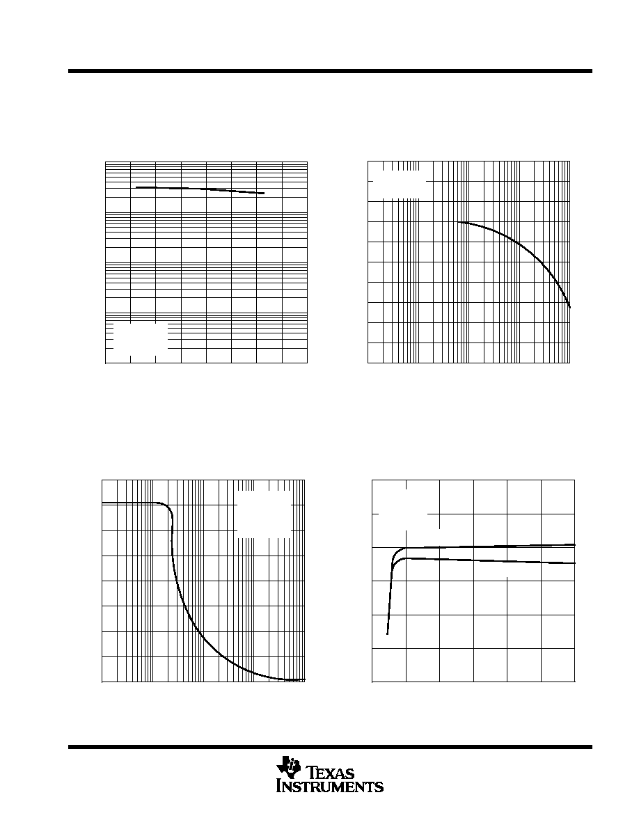
TYPICAL CHARACTERISTICS
Figure 1
≠ Input Bias Current ≠ nA
IBI
INPUT BIAS CURRENT (INVERTING INPUT)
vs
FREE-AIR TEMPERATURE
TA ≠ Free-Air Temperature ≠
∞
C
0
≠ 75
10
20
30
40
50
60
70
80
≠ 50
≠ 25
0
25
50
75
100
VCC = 15 V
VO = 7.5 V
II + = 0
Figure 2
0.9
TA ≠ Free-Air Temperature ≠
∞
C
MIRROR GAIN
vs
FREE-AIR TEMPERATURE
≠ Mirror Gain
+
/I
125
100
75
50
25
0
≠ 25
≠ 50
1.2
1.15
1.1
1.05
1
0.95
0.85
≠ 75
0.8
II + = 10
µ
A
VCC = 15 V
I ≠I
Figure 3
≠ Differential V
oltage
Amplification
VD
A
f ≠ Frequency ≠ Hz
LARGE SIGNAL
DIFFERENTIAL VOLTAGE AMPLIFICATION
vs
FREQUENCY
1
100
1 k
10 k
100 k
1 M
10 M
10
102
103
104
RL
10 k
RL = 2 k
VCC = 15 V
TA = 25
∞
C
Figure 4
≠ Differential V
oltage
Amplification
VD
A
VCC ≠ Supply Voltage ≠ V
LARGE SIGNAL
DIFFERENTIAL VOLTAGE AMPLIFICATION
vs
SUPPLY VOLTAGE
0
104
103
102
10
1
5
10
15
20
25
30
TA = 25
∞
C
RL = 10 k
Data at high and low temperatures are applicable only within the rated operating free-air temperature ranges of the various devices.
LM2900, LM3900
QUADRUPLE NORTON OPERATIONAL AMPLIFIERS
SLOS059 ≠ JULY 1979 ≠ REVISED SEPTEMBER 1990
5
POST OFFICE BOX 655303
∑
DALLAS, TEXAS 75265
TYPICAL CHARACTERISTICS
Figure 5
≠ Differential V
oltage
Amplification
VD
A
TA ≠ Free-Air Temperature ≠
∞
C
LARGE SIGNAL
DIFFERENTIAL VOLTAGE AMPLIFICATION
vs
FREE-AIR TEMPERATURE
1
≠ 75
10
102
103
≠ 50
≠ 25
0
25
50
75
100
125
VCC = 15 V
VO = 10 V
RL = 10 k
104
Figure 6
≠ Supply V
oltage Rejection Ratio ≠ dB
SVR
K
f ≠ Frequency ≠ Hz
SUPPLY VOLTAGE REJECTION RATIO
vs
FREQUENCY
0
100
10
20
30
40
50
60
70
80
90
100
1 k
10 k
100 k
1 M
400 k
40 k
4k
400
TA = 25
∞
C
VCC = 15 V
Figure 7
≠
Peak-T
o-Peak Output V
oltage ≠ V
f ≠ Frequency ≠ Hz
PEAK-TO-PEAK OUTPUT VOLTAGE
vs
FREQUENCY
0
1 k
2
4
6
8
10
12
14
16
10 k
100 k
1 M
10 M
II + = 0
RL = 2 k
VCC = 15 V
TA = 25
∞
C
¡¡
¡¡
¡¡
V
O(PP)
Figure 8
≠ Short-Circuit Output Current ≠ mA
OSI
VCC ≠ Supply Voltage ≠ V
SHORT-CIRCUIT OUTPUT CURRENT
(OUTPUT INTERNALLY HIGH)
vs
SUPPLY VOLTAGE
0
0
5
10
15
20
25
30
5
10
15
20
25
30
VO = 0
II + = 0
II ≠ = 0
TA = 0
∞
C
TA = 25
∞
C
Data at high and low temperatures are applicable only within the rated operating free-air temperature ranges of the various devices.