 | –≠–ª–µ–∫—Ç—Ä–æ–Ω–Ω—ã–π –∫–æ–º–ø–æ–Ω–µ–Ω—Ç: TGA1141 | –°–∫–∞—á–∞—Ç—å:  PDF PDF  ZIP ZIP |

TriQuint Semiconductor Texas : Phone (972)994-8465 Fax (972)994 8504 Web: www.triquint.com
Advance Product Information
Feb 4, 2000
1
33-36 GHz 2W Power Amplifier TGA1141
Primary Applications
∑
Military Radar Systems
∑
Ka Band Sat-Com
∑
Point-to-Point Radio
Note: Devices designated as EPU are typically early in their characterization process prior to finalizing all electrical and process
specifications. Specifications are subject to change without notice
Key Features
∑
0.25 um pHEMT Technology
∑
17 dB Nominal Gain
∑
31 dBm Pout @ P1dB,
∑
Psat 33dBm @ 6V , 34dBm @7V
∑
Bias 6 - 7V @ 1.5A
Chip Dimensions 4.13 mm x 3.3 mm
Performance Evaluation
Fixtured with Flare TFNs
33 to 36 GHz
> 17 dB nom, 34 - 35.2 GHz
> 17 dB nom, 33 - 36 GHz
~ 5 dB nom, 34 - 35.2 GHz
~ 5 dB nom. 33 ≠ 36 GHz
> 8 dB nom, 34 - 35.2 GHz
> 7 dB nom, 33 - 36 GHz
32.3dBm min. 34 ≠35.2 GHz
31.5dBm min, 34 ≠ 35.2 GHz
over temp.
> 20% +25C
Tested under ≠26, +25, &
+100C
Predict: -43C
< 1.5 A max over operating
frequency and Temp. range
+ 6 V
4.134 mm x 3.300 mm
13.6mm
2
Description
Frequency range
Small signal gain
Input return loss
Output return loss
Output power
PAE
Operating temperature range
Ids
Vds
Die size
25
26
27
28
29
30
31
32
33
34
35
32
33
34
35
36
37
Frequency (GHz)
P
out
(
d
Bm
)
P1dB_ave
Psat_ave
(
)
Wafer Lot 9918802-1, -2, -3, +6V, ~ 880mA
10
12
14
16
18
20
22
30
32
34
36
38
40
Frequency (GHz)
Sm
all-signal Gain (dB)
Performance Summary Table

TriQuint Semiconductor Texas : Phone (972)994-8465 Fax (972)994 8504 Web: www.triquint.com
Advance Product Information
Feb 4, 2000
2
Note: Devices designated as EPU are typically early in their characterization process prior to finalizing all electrical and process
specifications. Specifications are subject to change without notice.
TGA1141
S11,S22
S21
Measured Average Small Signal Data
(
)
Wafer Lot 9918802-1, -2, -3, +6V, ~ 880mA
10
12
14
16
18
20
22
30
32
34
36
38
40
Frequency (GHz)
Sm
a
ll-
s
i
gna
l Ga
in (
d
B)
(
)
Wafer Lot 9918802-1, -2, -3, +6V, ~ 880mA
-14
-12
-10
-8
-6
-4
-2
0
30
32
34
36
38
40
Frequency (GHz)
Input & O
u
tput Retur
n
Loss (dB)
S11
S22

TriQuint Semiconductor Texas : Phone (972)994-8465 Fax (972)994 8504 Web: www.triquint.com
Advance Product Information
Feb 4, 2000
3
Note: Devices designated as EPU are typically early in their characterization process prior to finalizing all electrical and process
specifications. Specifications are subject to change without notice.
TGA1141
30
30.5
31
31.5
32
32.5
33
33.5
34
34.5
35
32
33
34
35
36
37
Frequency (GHz)
P
out
(d
Bm)
+6V
+7V
(
)
10
12
14
16
18
20
22
24
26
28
30
32
33
34
35
36
37
Frequency (GHz)
PAE (
%
)
PAE@P1dB
PAE@Psat
25
26
27
28
29
30
31
32
33
34
35
32
33
34
35
36
37
Frequency (GHz)
Pout (dBm
)
P1dB_ave
Psat_ave
Psat vs Vd
PAE
Pout
Measured Power Data
TriQuint Semiconductor Texas : Phone (972)994-8465 Fax (972)994 8504 Web: www.triquint.com
Advance Product Information
Feb 4, 2000
4
Pout vs. Temperature Data Summary Matrix:
T= -26C
T= +25C
T= +100C
Freq (GHz)
min Pout mean Pout min Pout mean Pout min Pout
mean Pout
34
33
33
32.7
32.8
31.9
32
34.6
32.8
32.9
32.5
32.6
31.7
31.8
35.2
32.5
32.7
32.3
32.4
31.5
31.6
Ave. Pout (dBm)
32.8
32.9
32.5
32.6
31.7
31.8
TGA1141
(
)
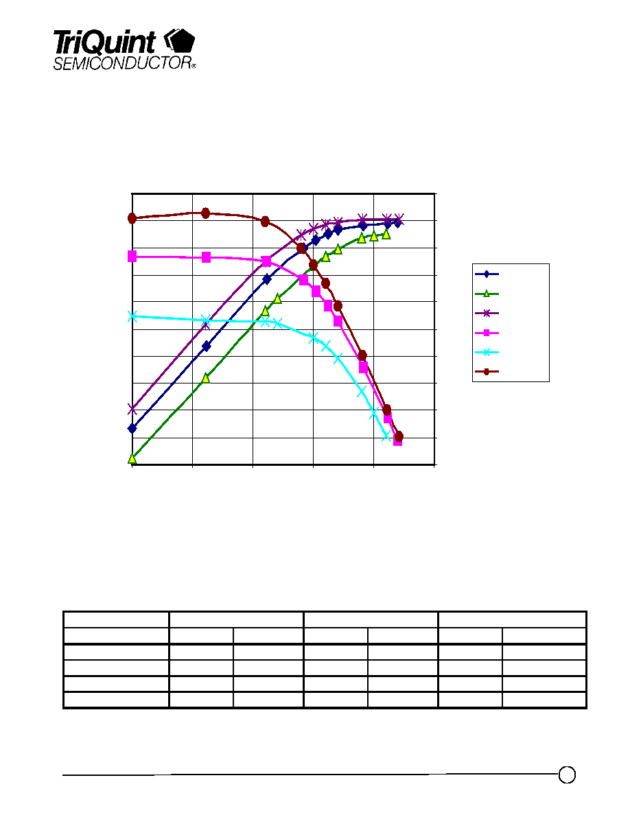
Pout, Gain vs. Pin at -26C, +25C and +100C
w9918802-1 Dev 2505: 34.0GHz +6V
15
17
19
21
23
25
27
29
31
33
35
0
5
10
15
20
25
Pin (dBm)
Pout
(
d
Bm
)
10
11
12
13
14
15
16
17
18
19
20
G
a
in
(d
B
)
Pout +25C
Pout +100C
Pout -26C
Gain +25C
Gain +100C
Gain -26C
Note: Devices designated as EPU are typically early in their characterization process prior to finalizing all electrical and process
specifications. Specifications are subject to change without notice.

TriQuint Semiconductor Texas : Phone (972)994-8465 Fax (972)994 8504 Web: www.triquint.com
Advance Product Information
Feb 4, 2000
5
Chip Assembly and Bonding Diagram
GaAs MMIC devices are susceptible to damage from Electrostatic Discharge. Proper precautions should
be observed during handling, assembly and test.
TGA1141
Note: Devices designated as EPU are typically early in their characterization process prior to finalizing all electrical and process
specifications. Specifications are subject to change without notice.

TriQuint Semiconductor Texas : Phone (972)994-8465 Fax (972)994 8504 Web: www.triquint.com
Advance Product Information
Feb 4, 2000
6
Reflow process assembly notes:
∑= AuSn (80/20) solder with limited exposure to temperatures at or above 300C
∑= alloy station or conveyor furnace with reducing atmosphere
∑= no fluxes should be utilized
∑= coefficient of thermal expansion matching is critical for long-term reliability
∑= storage in dry nitrogen atmosphere
Component placement and adhesive attachment assembly notes:
∑= vacuum pencils and/or vacuum collets preferred method of pick up
∑= avoidance of air bridges during placement
∑= force impact critical during auto placement
∑= organic attachment can be used in low-power applications
∑= curing should be done in a convection oven; proper exhaust is a safety concern
∑= microwave or radiant curing should not be used because of differential heating
∑= coefficient of thermal expansion matching is critical
Interconnect process assembly notes:
∑= thermosonic ball bonding is the preferred interconnect technique
∑= force, time, and ultrasonics are critical parameters
∑= aluminum wire should not be used
∑= discrete FET devices with small pad sizes should be bonded with 0.0007-inch wire
∑= maximum stage temperature: 200C
Assembly Process Notes
GaAs MMIC devices are susceptible to damage from Electrostatic Discharge. Proper precautions should
be observed during handling, assembly and test.
Note: Devices designated as EPU are typically early in their characterization process prior to finalizing all electrical and process
specifications. Specifications are subject to change without notice.