RS, NS
Vishay Dale
www.vishay.com
124
Document Number 30204
Revision 22-Mar-06
For technical questions, contact ww2bresistors@vishay.com
FEATURES
∑ High temperature coating (> 350 ∞C)
∑ Complete welded construction
∑ Meets applicable requirements of MIL-PRF-26
∑ Available in non-inductive styles (type NS) with
Aryton-Perry
winding
for
lowest
reactive
components
∑ Excellent stability in operation (typical resistance
shift < 0.5 %)
∑ Lead (Pb)-Free version is RoHS Compliant
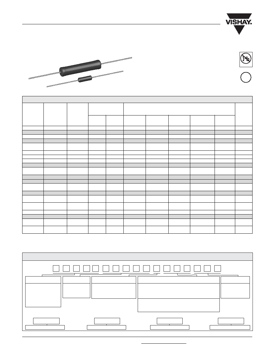
Wirewound Resistors, Military, MIL-PRF-26 Qualified,
Type RW, Precision Power, Silicone Coated
** Available tolerance for these Mil parts is ± 5 % for 1 and above, ± 10 % below 1 .
***Available tolerance for these Mil parts is ± 0.5 % & ± 1 % for resistance values 0.1 and above, ± 0.1 % for resistance values 0.499 and above.
****Vishay Dale RS models have two power ratings depending on operation temperature and stability requirements.
NOTE: Shaded area indicates most popular models.
STANDARD ELECTRICAL SPECIFICATIONS
RESISTANCE RANGE
MIL. RANGE SHOWN IN BOLD FACE
U
V
±
0.05 %
±
3 % thru
±
3 %,
±
5 %,
TYPE
thru
±
5 %
±
10 %
±
0.05 %
±
0.1 %
±
0.25 %
±
0.5 % &
±
1 %
±
10 %
g
RS1/8
RS-18
--
0.125
--
--
--
--
0.1 - 950
0.1 - 950
0.15
RS1/4
RS-1/4
--
0.4
--
1 - 1 k
0.499 - 1k
0.499 - 3.4 k
0.1 - 3.4 k
0.1 - 3.4 k
0.21
RS1/2
RS-1/2
--
0.75
--
1 - 1.3 k
0.499 - 1.3k
0.499 - 4.9 k
0.1 - 4.9 k
0.1 - 4.9 k
0.23
RS01A
RS-1A
--
1.0
--
1 - 2.74 k
0.499 - 2.74 k 0.499 - 10.4 k
0.1 - 10.4 k
0.1 - 10.4 k
0.34
RS01A...300 RS-1A-300
RW70***
1.0
--
--
0.499 - 2.74 k 0.499 - 10.4 k
0.1 - 10.4 k
0.1 - 10.4 k
0.34
1.0
--
0.1 - 2.74 k
RS01M
RS-1M
--
1.0
--
1 - 1.32 k
0.499 - 1.67 k 0.499 - 6.85 k
0.1 - 6.85 k
0.1 - 6.85 k
0.30
RS002
RS-2
--
4.0
5.5
0.499 - 12.7 k 0.499 - 12.7 k 0.1 - 47.1 k
0.1 - 47.1 k
0.1 - 47.1 k
2.10
RS02M
RS-2M
--
3.0
--
0.499 - 4.49 k 0.499 - 4.49 k 0.1 - 18.74 k
0.1 - 18.74 k
0.1 - 18.74 k
0.65
RS02B
RS-2B
--
3.0
3.75
0.499 - 6.5 k
0.499 - 6.5 k
0.1 - 24.5 k
0.1 - 24.5 k
0.1 - 24.5 k
0.70
RS02B...300 RS-2B-300
RW79***
3.0
--
--
_
0.499 - 6.5 k
0.1 - 24.5 k
0.1 - 24.5 k
0.1 - 24.5 k
0.70
3.0
--
--
0.1 - 6.49 k
RS02C
RS-2C
--
2.5
3.25
0.499 - 8.6 k
0.499 - 8.6 k
0.1 - 32.3 k
0.1 - 32.3 k
0.1 - 32.3 k
1.6
RS02C...17
RS-2C-17
--
2.5
3.25
0.499 - 6.8 k
0.499 - 8.6 k
0.1 - 32.3 k
0.1 - 32.3 k
0.1 - 32.3 k
1.6
RS02C...23
RS-2C-23
RW69**
--
3.25
--
--
--
--
0.1 - 32.3 k
16
3.0
0.1 - 2.0 k
RS005
RS-5
--
5.0
6.5
0.499 - 25.7 k 0.499 - 25.7 k 0.1 - 95.2 k
0.1 - 95.2 k
0.1 - 95.2 k
4.2
RS005...69
RS-5-69
RW74***
5.0
--
--
0.499 - 25.7 k 0.1 - 95.2 k
0.1 - 95.2 k
0.1 - 95.2 k
4.2
5.0
--
0.1 - 24.3 k
RS005...70
RS-5-70
RW67**
--
6.5
--
--
--
--
0.1 - 95.2 k
4.2
--
6.5
0.1 - 8.2 k
RS007
RS-7
--
7.0
9.0
0.499 - 41.4 k 0.499 - 41.4 k
0.1 - 154 k
0.1 - 154 k
0.1 - 154 k
4.7
RS010
RS-10
--
10.0
13.0
0.499 - 73.4 k 0.499 - 73.4 k
0.1 - 273 k
0.1 - 273 k
0.1 - 273 k
9.0
RS010...38
RS-10-38
RW78***
10.0
--
--
0.499 - 73.4 k
0.1 - 273 k
0.1 - 273 k
0.1 - 273 k
9.0
10.0
≠
0.1 - 71.5 k
RS010...39
RS-10-39
RW68**
--
13.0
--
--
--
--
0.1 - 273 k
9.0
--
11.0
0.1 - 20 k
POWER RATING****
P
25
∞
C
W
WEIGHT
(Typical)
MIL-PRF-26
HISTORICAL
MODEL
GLOBAL
MODEL
Available
Pb-free
RoHS*
COMPLIANT
e3
* Pb containing terminations are not RoHS compliant, exemptions may apply
GLOBAL MODEL
RESISTANCE
TOLERANCE CODE
PACKAGING
SPECIAL
VALUE
(See Standard
Electrical
Specifications Global
Model column
for options)
R = Decimal
A = ± 0.05 % B = ± 0.1 %
E70 = Lead (Pb)-free, Tape/Reel (smaller than RS005)
(Dash Number)
K = Thousand
C = ± 0.25 % D = ± 0.5 %
E73 = Lead (Pb)-free, Tape/Reel (RS005 & larger)
(up to 3 digits)
15R00 = 15
F = ± 1.0 % J = ± 5.0 %
E12 = Lead (Pb)-free, Bulk
From 1-999
10K00 = 10 k
K = 10.0 %
Lead (Pb)-free is not available on RW military type
as applicable
S70 = Tin/Lead, Tape/Reel (smaller than RS005)
S73 = Tin/Lead, Tape/Reel (RS005 & larger)
B12 = Tin/Lead, Bulk
GLOBAL PART NUMBER INFORMATION
New Global Part Numbering: RS02C10K00FS7017 (preferred part numbering format)
R
S
0
2
C
1
0
K
0
0
F
S
7
0
1
7
Historical Part Number example: RS-2C-17 10 k
1 % S70 (will continue to be accepted)
HISTORICAL MODEL
RESISTANCE VALUE
TOLERANCE CODE
PACKAGING
RS-2C-17
10 k
1 %
S70
www.vishay.com
125
RS, NS
Vishay Dale
Document Number 30204
Revision 22-Mar-06
For technical questions, contact ww2bresistors@vishay.com
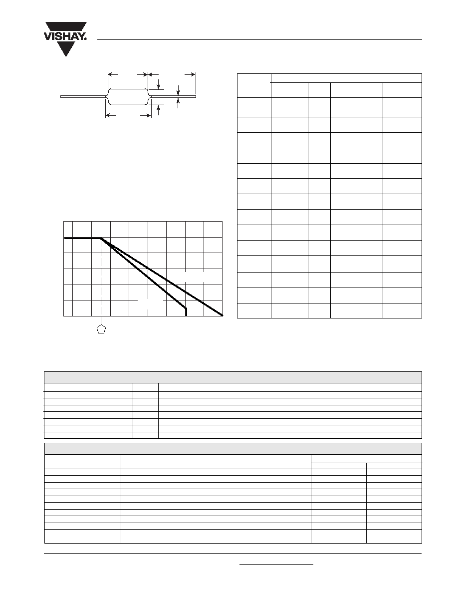
DIMENSIONS
Wirewound Resistors, Military, MIL-PRF-26 Qualified,
Type RW, Precision Power, Silicone Coated
GLOBAL
DIMENSIONS in inches [millimeters]
MODEL
MATERIAL SPECIFICATIONS
Element: Copper-nickel alloy or nickel-chrome alloy, depending on
resistance value
Core: Ceramic, steatite or alumina, depending on physical size
Coating: Special high temperature silicone
Standard Terminals: 100 % Sn, or 60/40 Sn/Pb coated Copperweld
Æ
.
NOTE: Military "RW" parts are only available with 60/40 Sn/Pb finish.
End Caps: Stainless steel
Deviations for RS-1/8: Thermoset silicone molded construction,
endcaps will be nickel-silver alloy and terminals will be tinned copper
Part Marking: DALE, Model, Wattage*, Value, Tolerance, Date Code
C
D
A
1.50
[38.10]*
Min.
B
A
B
C
D
(Max.)**
RS1/8
0.155 ± 0.015
--
0.065 ± 0.015
0.020 ± 0.002
[3.94 ± 0.381]
[1.65 ± 0.381]
[0.508 ± 0.051]
RS1/4
0.250 ± 0.031
0.281
0.085 ± 0.020
0.020 ± 0.002
[6.35 ± 0.787]
[7.14]
[2.16 ± 0.508]
[0.508 ± 0.051]
RS1/2
0.312 ± 0.016
0.328 0.078 + 0.016 - 0.031 0.020 ± 0.002
[7.92 ± 0.406]
[8.33] [1.98 + 0.406 - 0.787] [0.508 ± 0.051]
RS01A
0.406 ± 0.031
0.437
0.094 ± 0.031
0.020 ± 0.002
RS01A...300 [10.31 ± 0.787] [11.10]
[2.39 ± 0.787]
[0.508 ± 0.051]
RS01M
0.285 ± 0.025
0.311
0.110 ± 0.015
0.020 ± 0.002
[7.24 ± 0.635]
[7.90]
[2.79 ± 0.381]
[0.508 ± 0.051]
RS002
0.625 ± 0.062
0.765
0.250 ± 0.031
0.040 ± 0.002
[15.88 ± 1.57] [19.43]
[6.35 ± 0.787]
[1.02 ± 0.051]
RS02M
0.500 ± 0.062
0.562
0.185 ± 0.015
0.032 ± 0.002
[12.70 ± 1.57] [14.27]
[4.70 ± 0.381]
[0.813 ± 0.051]
RS02B
0.560 ± 0.062
0.622
0.187 ± 0.031
0.032 ± 0.002
RS02B...300 [14.22 ± 1.57] [15.80]
[4.75 ± 0.787]
[0.813 ± 0.051]
RS02C
0.500 ± 0.062
0.593
0.218 ± 0.031
0.040 ± 0.002
[12.70 ± 1.57] [15.06]
[5.54 ± 0.787]
[1.02 ± 0.051]
RS02C...17 0.500 ± 0.062
0.593
0.218 ± 0.031
0.032 ± 0.002
RS02C...23 [12.70 ± 1.57] [15.06]
[5.54 ± 0.787]
[0.813 ± 0.051]
0.875 ± 0.062
1.0
0.312 ± 0.031
0.040 ± 0.002
[22.23 ± 1.57]
[25.4]
[7.92 ± 0.787]
[1.02 ± 0.051]
RS007
1.22 ± 0.062
1.28
0.312 ± 0.031
0.040 ± 0.002
[30.99 ± 1.57] [32.51]
[7.92 ± 7.87]
[1.02 ± 0.051]
RS010
1.78 ± 0.062
1.87
0.375 ± 0.031
0.040 ± 0.002
RS010...39 [45.21 ± 1.57] [47.50]
[9.53 ± 0.787]
[1.02 ± 0.051]
RS010...38
1.78 ± 0.062
1.84
0.375 ± 0.031
0.040 ± 0.002
[45.21 ± 1.57] [46.74]
[9.53 ± 0.787]
[1.02 ± 0.051]
*On some standard reel pack methods, the leads may be trimmed to
a shorter length than shown.
NOTE: RS-1/8 terminal length will be 1.0" [25.4 mm] minimum.
**B (Max.) dimension is clean lead to clean lead.
NS NON-INDUCTIVE
Models of equivalent physical and electrical specifications are available
with non-inductive (Aryton-Perry) winding. They are identified by
substituting the letter N for R in the model number (NS-5, for example).
*Wattage marked on part will be "U" characteristic
-65 -50 0 50 150 250 350
AMBIENT TEMPERATURE IN
∞
C
Derating
120
100
80
60
40
20
0
RA
TED POWER IN %
CHAR. V
CHAR. U
25
RS005
RS005...69
RS005...70
*All R figures shown are maximum, based upon testing requirements per MIL-PRF-26.
PERFORMANCE*
TEST
CONDITIONS OF TEST
TEST LIMITS
Characteristic U
Characteristic V
Thermal Shock
Rated power applied until thermally stable, then a min. of 15 minutes at - 55 ∞C
± (0.2 % + 0.05 ) R ± (2.0 % + 0.05 ) R
Short Time Overload
5 x rated power (3.75 watt and smaller), 10 x rated power (4 watt and larger) for 5 seconds
± (0.2 % + 0.05 ) R ± (2.0 % + 0.05 ) R
Dielectric Withstanding Voltage 500 minimum for RS-1/8 thru RS-1A, 1000 for all others, duration of 1 minute
± (0.1 % + 0.05 ) R ± (0.1 % + 0.05 ) R
Low Temperature Storage
- 65 ∞C for 24 hours
± (0.2 % + 0.05 ) R ± (2.0 % + 0.05 ) R
High Temperature Exposure
250 hours at: U = + 250 ∞C, V = + 350 ∞C
± (0.5 % + 0.05 ) R ± (2.0 % + 0.05 ) R
Moisture Resistance
MIL-STD-202 Method 106, 7b not applicable
± (0.2 % + 0.05 ) R ± (2.0 % + 0.05 ) R
Shock, Specified Pulse
MIL-STD-202 Method 213, 100 g's for 6 milliseconds, 10 shocks
± (0.1 % + 0.05 ) R ± (0.2 % + 0.05 ) R
Vibration, High Frequency
Frequency varied 10 to 2000 Hz, 20 g peak, 2 directions 6 hours each
± (0.1 % + 0.05 ) R ± (0.2 % + 0.05 ) R
Load Life
2000 hours at rated power, + 25 ∞C, 1.5 hours "ON", 0.5 hours "OFF"
± (0.5 % + 0.05 ) R ± (3.0 % + 0.05 ) R
5 to 10 sec., 5 or 10 lb pull test (depending on size),
torsion test - 3 alternating directions, 360∞ each
Terminal Strength
± (0.1 % + 0.05 ) R ± (1.0 % + 0.05 ) R
PARAMETER
UNIT
RS RESISTOR CHARACTERISTICS
Temperature Coefficient
ppm/∞C
± 90 for below 1 , ± 50 for 1 to 9.9 , ± 20 for 10 and above
Dielectric Withstanding Voltage
V
AC
500 minimum for RS-1/8 thru RS-1A, 1000 minimum for all others
Maximum Working Voltage
V
(P x R)
1/2
Insulation Resistance
1000 Megohm minimum dry, 100 Megohm minimum after moisture test
Terminal Strength
lb
5 minimum for RS-1/8 thru RS-1A, 10 minimum for all others
Solderability
≠
MIL-PRF-26 type - Meets requirements of ANSI J-STD-002
Operating Temperature Range
∞C
Characterisitic U = - 65/+ 250, Characteristic V = - 65/+ 350
TECHNICAL SPECIFICATIONS
Two conditions apply:
1. For NS models, divide maximum resistance values by two
2. Body O.D. on NS-2C may exceed that of the RS-2C by 010"
